LTO (Lithium Titanate Oxide) – The Ultimate Battery for Dash-Cam parking mode (DIY)

Today I received the new charger, check the side by side image for size difference, the height is about 4 mm taller.
It is rated at 25A continuous, so the terminals, capacitors and inductor are much beefier, but still quite small compare to old technology/generation chargers.

Specs are here, scroll the page and press "View More" for details.


IMG_7611.JPG
 
According to the specs, the newer one can handle a good bit more heat - 125c!! Not really a surprise, given the larger current rating. Still no integral backflow control, though. I could swear I read somewhere that the smaller one had an anti backflow component in it, but I can’t find any reference to it now. Oh well. Maybe it was a function of wishful thinking.

Should be able to jack up the battery charge rate, provided you run directly to your car’s battery. The battery cable that I linked a few posts ago is actually 11g wire, so it has plenty of carrying capacity. It’s my new favorite wire, but it’s also a bit expensive in the $/ft category.

I have to say that I’m amazed by the voltage/current conversion capability of such a small board! Very impressive! I’m used to enormous sized caps (35,000uF up to 250,000uF) in a linear power supply for my Class A amps. Those 470uF caps on the new board still look tiny…
 
Last edited:
Yikes! I just installed the little red anti-backflow diode board from amazon and nearly right away, I’m seeing temps of 112c, a 90c rise over ambient while recharging my LTO battery!! This is with a charge rate of 7.4A on a fully depleted battery. I wrapped the solder joints in some kapton high temp tape to prevent shorts inside the box, but left the diodes uncovered.

Strangely, after about 10-15 mins, the board temp is now down to 35c, or about 13c over ambient. This is much better! Not sure why it was so high at the onset and then declined, though. Current flow is still 7.4A. Break in period? High resistance on charging a dead battery? Not sure what is going on here. I stopped the charge after about an hour to let things cool down for another hour and then restarted the charge. Anti backflow board only hit 50c this time, then after some time dropped down to 30c or so.

Orange LED on the charger board is still illuminated…

Tomorrow, my new XT60 wire will arrive and I’ll finish the direct to battery hardwire install on my Volvo. Even the battery wire harness on the Volvo is complex, but I found a place for an easy add to a direct connect to the pos terminal that won’t interfere with battery changes or anything else. The negative terminal definitely has a current flow meter for the BMS, so the negative charge wire will go to chassis ground.
This temperature spike is hard to explain, maybe the thermometer reading was wrong? You could probably check it by touch, but 125°C is much higher than the boiling point of water and will burn your fingers.

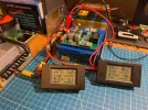
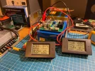
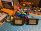
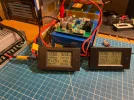
I currently have 4 different anti-reverse "ideal diodes".
The same Red one rated at 15A, shown wired as tested, and the other 3 are shown from left to right on the bottom of image:
15A Grin, 20A Grin (small square) and 50A Black.

Here are the test results for the 15A Red Diode:
Ambient temperature 25°C
Test duration about 30 min, Constant Current, Voltage and Power were gradually growing as battery was charging.

When charging at 8A charging:
The Current drop negligible, about 0.01A
The voltage drop is about 0.14V
The power consumption is 0.14V x 8A = 1.12W
The Diode temperature gradually increased from 25°C ambient to 38°C and stabilized there
The Charger temperature (Inductor) stabilized at 56°C

When charging at 10A charging:
The Current drop negligible about 0.01A
The voltage drop is about 0.17V
The power consumption is 0.17V x 10A = 1.70W
The temperature gradually increased and stabilized at 45°C
The Charger temperature (Inductor) stabilized at 65°C

The Diode average efficiency is about 98.7%

There were no temperature, voltage or current spikes, nothing unexpected.
I tested including from a completely discharged battery at about 9V and at mid-point charge about 12V

I will test and post the results for the rest of the Diodes for comparison.

IMG_7620.JPG
 
Last edited:
Do not buy/use the 15A rated long Grin Diode with black heatsink, I am not sure what is it, but it is not an Ideal Diode.

With the 8A charging, the voltage drop is about 0.72V and the temperature reached 85°C in about 3 minutes, after which I stopped the test.

In all fairness, looking at the Amazon description now, it never claimed to be an Ideal diode.
 
Definitely over 100c. My first test was a finger touch. I was surprised at how hot it was, so I got my temp gun to make a measurement.

I connected my diode a bit differently than you did. Perhaps this is part of the reason for the high temp, but I doubt it. I inserted it into the red positive voltage leg between the charger and the battery as shown in your image. I was careful to orient it properly. The negative side of the red ideal diode board is just a pass through (that also helps power the circuit), the trace on the PCB is continuous from input to output. Because I didn't want to break the nice heavy wire from the negative charger output to the BMS input, I just ran a small gauge wire from the charger’s negative output to the negative side of the diode board. All it really needs is a ground connection for the control components on the board.

The middle and right hand diode boards in your image at the bottom show this same manner of connection. I think I’ll pick up a different diode board and play around some more.
The way you connected, is how the most Ideal Diodes are designed to be connected, with a very small negative terminal, as you noted with the other two in my picture.
And that is how I am going to test those two.

However the Red one has full-sized negative terminals so I connected as shown, but I also doubt that makes the difference, later I can connect it as you did to check.
 
Here are two images of my car battery tap for LTO battery charging. The Volvo battery connection/installation is a bit complex - they seem to have an "over design it" type of philosophy for stuff. The battery is located in the trunk and you have to remove the inner tailgate and then the side trunk liner to expose the battery. When you finally see it, it's still covered up with the clip on plastic terminal guard (second image). It takes a little while to open the clips so you don't break any of them.

Once the cover is removed, you can see a metal band that leads to several voltage take off points, each through its own dedicated fuse. I used the screw post indicated by the yellow arrow- it's a direct tap from the battery positive that is always live. In the lower left corner of the image, you can see the current flow sensor for the BMS on the battery negative terminal.

IMG_10354.JPG


I added a 20A inline fuse to my new power tap and restored the plastic cover. The final battery hookup is shown below. Tapping power this way does not interfere with or otherwise complicate battery replacement. My battery checker indicates I'll likely be doing this job in a few months. That's the original battery and it's now over 5 years old...
IMG_10355.JPG


I inserted a 30A time delay relay into the middle of the +12v line using a 12g relay harness. The relay coil is powered with an add-a-fuse that I put in the fusebox that goes on and off with the car's ignition. The 12v utility outlet in the trunk stays live for several minutes after turning off the car, so drawing the 12v power supply from the battery is a better solution for more than one reason. The ground wire for the LTO battery and relay coil are returned directly to a chassis ground harness that is just below the fusebox. Testing happens tomorrow...

In other news, the LTO battery in my son's car is now charging more consistently now that it's wired directly to the battery. During the week that it stopped charging, the utility outlet plug must have been making intermittent contact as it melted because some days the battery would charge more than others and I was confused by the variability. It's rock steady now and it looks like I'll need to back down the charging current a little.
 
Last edited:
Car wiring confirmed. Charge to the LTO box begins about 8s after the car is started. Ignition/ACC On does not trigger the relay, so this is exactly what I was looking for - it won't drain the cars main battery while the engine isn't running. The relay disengages and kills power to the LTO box within about 3s of turning the car off. The high current wiring goes directly to the battery positive terminal with a 20A fuse and to the chassis ground with 11g wire. The harness for the time-delay relay is 12g wire. All power wires are wrapped in a protective sheath and zip tied to existing wire harnesses to keep everything out of the way and from rubbing anywhere where it shouldn't. Dashcam starts up with the car's ignition and goes in and out of parking mode as it should.

Now I just need to attend to that really hot anti-backflow diode. I just ordered one from AliExpress along with some additional time-delay relays just to have some replacements on hand.
 
OMG, this is the most complicated car battery installation I have ever seen!. It's crazy.
Volvo definitely did everything they could to discourage the owner from replacing the battery by making it a dealer job.
 
Yeah, it’s an intimidating job for sure. That big wiring harness on top lifts off by releasing two more clips that hold it to the top of the battery after undoing the positive battery terminal clamp. I suspect I’ll be changing the battery out as the weather gets colder. Then, after changing the battery, you need to do a BMS reset, too. This is after removing two separate pieces of trunk liner, too… There is a reason why the dealership charges between 1.5 and 2.0 hours of labor to replace the main battery 🙄

Now that I've wired the LTO pack directly to the Volvo battery, I need to see if there is still a current backflow when I first start the car. I was watching the voltage out of the XT60 connector while I was testing things yesterday. Following the 8s delay after starting the car, the XT60 charge wire is at about 12.3v, which is just battery voltage level. It seems to take another few seconds for the car's BMS to begin charging the battery from the alternator. When this kicks in, the battery voltage slowly rises from 12.3 to about 14.6v. It hangs out there for a few more seconds, then drops down to around 14.4v or so where it maintains steady state. I presume it was the car's battery that was sinking all of the LTO backflow current beforehand. I'm not sure if backflow behavior will continue with a direct battery connection or not. I'll bypass my backflow diode and see what happens. My son's LTO BMS does not report any backflow with a direct battery connection and time delay relay in the Mustang. I didn't put a backflow diode in the Mustang LTO box, it doesn't seem necessary.
 
Last edited:
Here is the test results for the Green square 20A Diode:
Ambient temperature 25°C
Test duration about 30 min, Constant Current, Voltage and Power are gradually growing as battery was charging.
Tested at mid-point charge about 12.5V

When charging at 8A:
The Current drop negligible, about 0.01A
The voltage drop is about 0.11V
The power consumption is 0.11V x 8A = 0.88W
The Diode temperature gradually increased from 25°C ambient and reached 33°C and

When charging at 10A:
The Current drop negligible about 0.01A
The voltage drop is about 0.14V
The power consumption is 0.14V x 10A = 1.40W
The temperature gradually increased and reached 37°C

The Diode average efficiency is about 99%

There were no temperature, voltage or current spikes, nothing unexpected except read below.

This Ideal Diode is more efficient than the red one and would be a great option, but I have found that after power supply is turned off, sometimes it does not block the reverse flow voltage, however as soon as I connect any load to this reverse flow voltage it disappears, there is no backflow current.
Not sure what to think, may be it is a design intent, may be some kind of fault, not sure.

EDIT: added pictures
IMG_7624.webp

IMG_7626.webp
 
Last edited:
Ballpark 1w dissipation isn't bad at all for passing 8-10A of current! In the context of "left over" voltages, are those little brown surface mount parts caps or resistors? They look too big to be resistors (which are usually black), but your image of the board is from kinda far away, so I can't read any labels next to those parts. If they are caps, that's likely where the "ghost voltage" is coming from.

Overall, that's a pretty nice result! Thanks for continuing to share your test results.

I ordered these two (both without the screw terminals for lower profile installation) from AliExpress, so I have to wait a little while for them to arrive:
https://www.aliexpress.us/item/3256803401816483.html (same as in your image)
and
https://www.aliexpress.us/item/3256805499983692.html (dual devices in parallel)
Added pictures to my previous post
There are no markings, I think they are caps, see the link for similar:

I will test and post that 50A black one today, hopefully

Also I have this one on order, chasing the small size, and it looks like this one does't need negative and claims no voltage drop, will check it 🙂.

 
Last edited:
And the test results for the Black 50A Diode:
Ambient temperature 25°C
Test duration about 30 min, Constant Current, Voltage and Power are gradually growing as battery was charging.
Tested at mid-point charge about 12.5V

When charging at 8A:
The Current drop negligible
The voltage drop is about 0.13V
The power consumption is 0.13V x 8A = 1.04W
The Diode temperature gradually increased from 25°C ambient and reached 32°C and

When charging at 10A:
The Current drop negligible
The voltage drop is about 0.16V
The power consumption is 0.16V x 10A = 1.60W
The temperature gradually increased and reached 36°C

The Diode average efficiency is about 98.9%
There were no temperature, voltage or current spikes, nothing unexpected and no back-flow voltage.

In terms of efficiency, this ideal diode is between 15A red and 20A green, but produces the least amount of heat.

IMG_7635.JPG

IMG_7645.JPG
 
OMG, this is the most complicated car battery installation I have ever seen!. It's crazy.
My first car was a 1967 Volvo 121, one year younger than myself, i will not get a new Volvo that is for damn sure, but with a little lotto money i might pick up a old 121 again and come full circle.
 
The Diode average efficiency is about 98.9%
There were no temperature, voltage or current spikes, nothing unexpected and no back-flow voltage.

In terms of efficiency, this ideal diode is between 15A red and 20A green, but produces the least amount of heat.
Cool! I just ordered that one last night….

Tested the new wiring in the car with my LTO box. No backflow with the diode in place and a direct battery wire on a fully charged 16v LTO. My next experiment will be to bypass the backflow diode and see if the good behavior continues. Maybe the diode is not necessary with the new wiring configuration?

My first car was a 1967 Volvo 121, one year younger than myself, i will not get a new Volvo that is for damn sure, but with a little lotto money i might pick up a old 121 again and come full circle.
Ha! I really enjoy mine, but it does feature some complex construction and parts are a bit on the expensive side compared to my previous Subarus. My warranty is good until 2029, so Volvo owns the problems until then. So far, I haven’t had any. I’m thinking my next car will likely be a battery car.

The 121 is a nice looking car! Seems that they are rare enough at this point not to be a search option on CarGurus.com…
 
Quick update on 15A Red Diode,

I wired it as all other Diodes, bypassing the negative power wire and using negative thin wire/jumper to connect to Diode's negative terminal.
The Diode perform exactly the same as previously with one exception, at 10A charging the temperature was about 42°C or about 3°C cooler.
 
Interesting result, GPak! Lower temps seem to fit my expectations by removing a second heavy current flow from the tiny board. I'm still not happy with the enormous temps I saw in mine, I'm wondering how/why that happened. I don't have much trust in my specific sample. Others will arrive in a week or two. In the mean time, I want to experiment with the necessity of a diode at all in with my new direct-to-battery wiring with time-delay relay in place.
 
Tested this 25A charger, for about 30 min for each current setting (ref. Post # 181).
https://www.aliexpress.us/item/3256...t_main.22.36121802vsbbBd&gatewayAdapt=glo2usa

With 8A charging - in a 30 min the highest temperature (inductor) reached 42°C (20A version was 56°C), efficiency is about 96.1%
With 10A charging - in a 30 min the highest temperature reached 48°C (20A version was 65°C), efficiency is about 95.4%
With 12A charging - in a 30 min the highest temperature reached 53°C, efficiency is about 94.5%
With 16A charging - in a 30 min the highest temperature reached 69°C (20A version was 105°C), efficiency is about 92.6%
With 20A charging - in only a 15 min the temperature reached about 90°C, and the charger slowly drops the current, I guess some kind of protection, efficiency is about 91%

I think 16A is probably a safe maximum continuous current limit for this charger.
This is about 204W average charging rate for the 4S LFP battery and about 220W average charging rate for the 6S LTO battery.
 

Attachments

  • IMG_7647.webp
    IMG_7647.webp
    415.5 KB · Views: 120
  • IMG_7650.webp
    IMG_7650.webp
    380.9 KB · Views: 110
  • IMG_7654.webp
    IMG_7654.webp
    376.9 KB · Views: 110
  • IMG_7656.webp
    IMG_7656.webp
    379.5 KB · Views: 117
Back
Top