LTO (Lithium Titanate Oxide) – The Ultimate Battery for Dash-Cam parking mode (DIY)

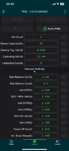
-When charging, calibrate the charging current (A) in the app to match the actual charging current measured at the main positive battery cable.
-When discharging, calibrate the discharging current (A) in the app to match the actual discharging current measured at the main positive battery cable.
-Note: The minimum discharge current allowed for calibration in the app is 0.50A or may be slightly higher.

Despite calibration, over time the JK-BMS cannot accurately reflect the battery's SoC due to the very low parking current draw and the accumulation of self-consumption error.

However, for an LTO battery, we can use the voltage to accurately estimate the SoC.
Here is why:
-LTO batteries have a more linear and sloping charge/discharge curve, with voltage increasing more steadily throughout the charge/discharge, making it easy to determine the state of charge by voltage alone.
-In contrast, LFP batteries have a very flat charge/discharge curve, where the voltage stays almost constant for most of the charge/discharge cycle, making it difficult to determine the state of charge by voltage alone.
 
Last edited:
-When discharging, calibrate the discharging current (A) in the app to match the actual discharging current measured at the main positive battery cable.
For some reason, I can't make this work. I connected a 27R 12w resistor across the red and black terminals that produced a current of 0.58A. When I type in a value and click "OK" I just get a Send Failure. I can't do the charge current calibration yet, I have to drain the battery more so the charge current will hold steady for a little while and give me time to match them up (if it lets me). I've been running a 5w camera in parking mode for more than 30 hours now and the battery has barely lost one full volt 🙂

I think it might be time to reach out to the JiKong tech support...

Calibrating Current Fail.webp
 
I was getting the same warning using 2ch dashcam drawing around 0.3A.
I then used an electronic load to find the lowest current draw at which I could calibrate, and in my case I think it was around 0.5A-0.6A.

Try discharging the battery at a higher current, perhaps around ±0.7A.
You could use a pair of dash cams with a total of 4 channels.
I think this current will be sufficient for calibration.
 
Guess I'll just start stacking up power resistors, then. The 0.58A draw resulted from putting one 27R resistor across the outputs. I have a few more that I can add in parallel that will drive the current higher. That should be enough if there are lower limits to being able to perform the calibration. By the time I get home tonight, the batteries should be sufficiently depleted to allow fixed current charging for a while, which will hopefully allow me to calibrate charge current too. The battery voltage level was only down to 14.5v after nearly 40 hours of runtime with a 5w, 3-channel camera. I think I've achieved my goal of longer runtime 🙂

I have noticed a few other differences between the older and newer JK BMS units: The lowest setting for the "Balance Trigger Voltage" among cells is 0.001 in the older BMS, but now is 0.003v in the newer BMS. The same is true with the "Continued Discharge Current" and "Discharge OCP Delay" - all have higher minimums than the older BMS. This isn't much of a big deal because the charger has an anti-backflow capability built into it. Also, the older BMS draws its operational power from the cell balance wires (thin black and last red wires). The newer BMS draws is operational power from the heavy gauge B- and P- wires.

My "Smart Sleep" function is also not reliable to waking up with ignition, sometimes it works sometimes it doesn't.

The QR code on the BMS links to a ton of documents. In one of the instruction documents, I found the following passage:
"After confirming that the above conditions are correct, the BMS can be powered up. The BMS has no power-on control switch and is designed for charging activation mode (charger voltage is 5V higher than battery voltage), that is, after the battery is assembled, you need to connect the charger to make the BMS work."

Perhaps differences in the battery state of charge explains the intermittent nature of the "wake up with ignition" function working. Hard to tell, the manual is not written with precision. I wonder if the 5v delta for "wake up" is implemented in the hardware or the software? Software features are much easier to change...
 
Success! I was able to calibrate the current draw by using two 27R 10w resistors in parallel, this created a draw of 1.08A as measured with my DMM inline with the positive battery terminal.. Thank you for the tip about the minimum draw rate needed for calibration! I'll calibrate charging current tomorrow, the battery needs to be drawn down some more.

Edit: Ah, I get it now. If the Calibrating Current shows 0.0 in the app, then there isn't enough current in or out to allow calibration to occur.

After 50+ hours of a 5.6w draw, battery voltage is still north of 14.25v!
Now at 66+ hours and still have more than 14v available.
 
Last edited:
....
The QR code on the BMS links to a ton of documents. In one of the instruction documents, I found the following passage:
"After confirming that the above conditions are correct, the BMS can be powered up. The BMS has no power-on control switch and is designed for charging activation mode (charger voltage is 5V higher than battery voltage), that is, after the battery is assembled, you need to connect the charger to make the BMS work."
Perhaps differences in the battery state of charge explains the intermittent nature of the "wake up with ignition" function working. Hard to tell, the manual is not written with precision. I wonder if the 5v delta for "wake up" is implemented in the hardware or the software? Software features are much easier to change...
Interesting!
Based on that I just briefly tested my 5S LTO battery to see if voltage difference between the battery and charging CV makes the difference for "Smart Sleep" and it so, what would be the minimum required voltage difference to wake up.
(I was manually turning off the BMS by long pressing the on/off button to speed up the test, hopefully this is the same as "Smart Sleep")

So for the 5S LTO battery, my charger's CV is set to about ±13.4V. (1.68V per cell)
When the BMS goes into sleep mode at battery voltages up to 12V (2.4V per cell) then it will wake up with charging due to 1.4V difference (13.4V-12.V=1.4V)
If the battery voltage is above 12.5V (2.5V), it doesn't wake up.
And anything in between 12V -12.5V battery is not 100% reliable. (requires more precise testing)
So, it looks like the “Smart sleep” works as a kind of “timeout” and a kind of “battery low voltage protection” combination.

For the 6S LTO, set the “Vol. Smart Sleep(V) to ±14.5V and see if the battery will wake up with charging at that voltage.
If it works then above ±14.5V the BMS will not enter "Smart Sleep", but will enter below 14.5V and will wake up with charging.
If it won't wake up at 14.5V with charging, lower the battery voltage until it does.
 
I was able to calibrate both the charge and discharge current. The BMS was pretty close, but I made it match precisely for a charge current of about 7.5A and a discharge current of about 1.05A My DMM will read up to 10A with the current passing through the meter, but I didn't want to push it to the max for calibration purposes. I think current measurements are properly calibrated now.

On to sleep mode experiments: I'm not sure if what I'm doing is actually testing what I think it is testing... but... I experimented with a number of settings for the "Vol. Smart Sleep(V) setting and manually turned off the BMS with a long press of the button and then applied my external PSU to simulate turning on the car to see if the BMS would wake up. I am making the assumption that manually turning off the BMS with a long-press of the button is actually equivalent to the BMS going to sleep by itself with the "Time Smart Sleep" setting - which may or may not be accurate.

I set the "Vol. Smart Sleep(V) to 2.56v, 2.50v, 2.30v, 2.10v, 1.90v, 1.70v, and 1.50v and then turned off the BMS. In all cases, the BMS woke up and the camera turned on when I applied power to the battery box (simulating turning on the car). The battery voltage for this set of tests was about 14.1v.

I didn't actually test to see if the BMS wakes up after going to sleep by itself using the "Time Smart Sleep" setting as the lowest setting is 1hr. That will take much longer to test. Obviously, this messed with my measurment of how long the battery pack will power my camera... Oh well...

I just ordered a 180w "DL24/P Color 2.4" DC USB tester electronic load lithium battery capacity monitor discharge charge power meter supply checker APP" to run down the battery faster than will happen with a 5w camera, but it will take another 2 weeks for it to show up.

I suspect waiting for a 5w power draw to run down the battery could take week or two...
 
Last edited:
...
I just ordered a 180w "DL24/P Color 2.4" DC USB tester electronic load lithium battery capacity monitor discharge charge power meter supply checker APP" to run down the battery faster than will happen with a 5w camera, but it will take another 2 weeks for it to show up.
I use the same electronic load, it is a very good and affordable option.

I suspect waiting for a 5w power draw to run down the battery could take week or two...
Assuming the system efficiency is 80%, then with a 5W load the battery will take about 7.5 days to discharge! 👍
EDIT: See Eric's post below !
 
Last edited:
My 276Wh battery exhibited about 95% efficiency. I got 75 hours with a 3.5w draw before the battery died (262w). With three cameras running in parking mode, I'm getting about 20 hours from the smaller battery.

Quadruple the storage capacity for the new battery, with a similar efficiency rating (maybe not, these are used batteries) and a slightly higher draw of 4.5w (camera + hardwire kit) + 0.7w for the BMS should come closer to 0.95*1104/5.2w = 202 hours or 8.4 full days. So, yeah, anywhere between 7 and 9 full days is my ballpark estimate for single camera in parking mode.

For running three cameras while I'm parked at work, I anticipate about 80 hours of battery life, which gives me just shy of 2 weeks if I run without additional plug-in recharging. Throw in running errands around town and it's more likely I'll get closer to 2.5 or 3 weeks before I need to plug it in to recharge. Should work out pretty well.
 
Yes, you're right, I confused it with charging efficiency (the charger, the relay, the wires, the high current...)😕
I've edited my previous post.
 
I repeated the test on my 5S LTO and can confirm that the maximum battery voltage at which the BMS will reliably wake from sleep mode is 12V (2.4V per cell).
This is about 1.4V lower than my constant charging voltage (CV=13.4V).
Conclusion:
- To wake the BMS from sleep mode, a minimum difference of about 1.4V between the battery voltage and the charger's constant voltage (CV) is required.
– Therefore, to ensure the battery always wakes from sleep mode, the "Vol. Smart Sleep (V)" - the cell voltage above which the “Smart Sleep” function is disabled, must match the maximum battery voltage at which the BMS is guaranteed to wake (in my case, for the 5S LTO, this is 2.4V as tested above).
Thus, the "Smart Sleep" functionality will be limited to a battery charge level of about 75%.

Later today, I'll also post the test results on my 6S LTO.
 
I completed the same test on my 6S LTO and can confirm that the maximum battery voltage at which the BMS will reliably wake from sleep mode is 14.64V (2.44V per cell).
This is about 1.46V lower than my constant charging voltage (CV=16.1V).
Conclusion:
- To wake the BMS from sleep mode, a minimum difference of about 1.44V between the battery voltage and the charger's constant voltage (CV) is required.
– Therefore, to ensure the battery always wakes from sleep mode, the "Vol. Smart Sleep (V)" - the cell voltage above which the “Smart Sleep” function is disabled, must match the maximum battery voltage at which the BMS is guaranteed to wake (in my case, for the 6S LTO, this is 2.44V as tested above).
Thus, the "Smart Sleep" functionality will be limited to a battery charge level of up to 80%.

P.S.
I'm so glad we finally solved the "mystery" of the "Smart Sleep" feature.
I think 0-80% battery charge is a good enough range for "Smart Sleep" functionality.
Now I can finally use it. I used to turn it off out of uncertainty.

We still need to remember that If the parking current consumption is less than 0.57A, the BMS will start counting down to Sleep mode, regardless of whether the dash cam is working.
Therefore, I'll set the Smart Sleep timeout to 5 hours.
This will basically duplicate my dashcam’s parking time duration, but will also turn off the battery itself.

@EricSan - I can't wait to see your test results with the latest BMS model.
 
Last edited:
The interesting part about your tests with 5S and 6S battery strings is that you've come up with consistent results of ~2.4v per cell for the BMS to wake up. I agree, the 0-80% state of charge that allows the BMS to wake up seems sufficient. I'm thinking I'd set mine to go to sleep after about 9 hours. That way, it would last for the entire day at the office, would only remain on for part of the night, and turn itself off over the weekend.

The other thing that I'm wondering about is the new "SOC-100% Volt.(V)" setting in the BMS. I wonder if this has the capability of ramping down the charge current as the voltage approaches the 100% mark. If so, is it possible to dial up the voltage output of the charger board and just let the BMS handle everything? This might allow the smart sleep function to wake up across the entire battery voltage range. Just musing here... A more detailed user manual would be useful.

I have to wait a little bit for my battery discharge device to arrive before I can safely handle high current discharge rates. I also need to pick up a set of high-current battery terminals so I have a place to connect the battery discharger - maybe something like this (I'm all out of amplifier speaker terminals):

Using the battery terminal for discharge bypasses the BMS, so it doesn't realize that the battery is being drawn down. Definitely want to experiment further, but I now I have to wait. This is the boring part, just watching the battery slooooooooooowly run down 😉
 
...
The other thing that I'm wondering about is the new "SOC-100% Volt.(V)" setting in the BMS. I wonder if this has the capability of ramping down the charge current as the voltage approaches the 100% mark. If so, is it possible to dial up the voltage output of the charger board and just let the BMS handle everything? This might allow the smart sleep function to wake up across the entire battery voltage range. Just musing here... A more detailed user manual would be useful....
Good question!
It looks like I used the wrong voltage for this setting.
According to the AI, this voltage is for calibrating the coulomb counter and should be very close to the "Cell OVP(V)" value, maybe one notch (0.01V) lower!
Mine was 0.04 V lower than "Cell OVP(V)".
See the links:
and
 
Last edited:
Interesting! All of this would be so much more straight forward if they’d just publish a decent user manual.

EDIT: with a Cell OVP(V) setting of 2.7v (default for LTO cells), the highest “SOC-100% Volt.(V)" that the BMS will accept is 2.67v (the default setting is 2.65v).
 
Last edited:
Attached are my updated voltage settings.

I can't/don't want to set the OVP(V) cell voltage to 2.7V - to do that, I'd have to open the box and increase the charger's output voltage (CV) accordingly to reach that voltage.
Currently it is 13.4V which corresponds to 2.68V per cell (for 5S battery), and it will take long time to get to 2.7V if it ever does.

So I set the "Cell OVP(V)" voltage to 2.69V and for the last 15-20 minutes of charging the BMS shows 0A charging but in reality the charging continues slowly, eventually reaching 2.69V at which point the charging shuts off with the message "Battery fully charged".

I set the "SOC-100% Volt.(V)" to 2.68V in my BMS without any problems.
 

Attachments

  • IMG_8861.webp
    IMG_8861.webp
    75.6 KB · Views: 103
Last edited:
It seems that we've discovered another difference between BMS firmware versions: the Cell OVP(V) setting. I'm guessing the development team at JK is still dialing in what they consider to be optimal parameters for working with LTO cells. I suppose that's to be expected (somewhat) as LTO cells are not super common? Just guessing...
 
....is it possible to dial up the voltage output of the charger board and just let the BMS handle everything? This might allow the smart sleep function to wake up across the entire battery voltage range. Just musing here...
Okay, let's think about it...
For the Smart Slip feature to operate across the entire practical/resting voltage range, the charger's constant output voltage (CV) must be at least 1.44 V higher than the resting voltage of a fully charged battery.
Assuming a fully charged battery's resting voltage is 15.6 V (2.6 V per cell), the constant charging voltage (CV) must be at least 15.6 V + 1.44 V = 17.04 V (CV), or 2.85 V per cell.
The battery management system (BMS) will still be set to "Cell OVP(V)" = 2.7V (this is now the only over voltage charge protection and is a single-point failure).

With 17.04VC charging, the battery will charge faster without significantly reducing the charging current at the end of the charge.

As a result:
- The cells will experience greater stress during charging, which may shorten their lifespan.
- The imbalance will grow much faster, and one cell will reach the 2.7V limit much faster than the others, so the overall battery voltage will never approach the full 16.2V (2.7V per cell).
- The battery won't have time to balance during charging, only after it's complete.

All of the above is less critical for LTO than LFP.

I think the maximum voltage of 2.8V is safe for LTO cells.
Perhaps this would be an acceptable compromise for charging the battery with 16.8V(CV)? (6*2.8V)
Then the “Smart Sleep” would be effective starting at about 15.4V (2.57V per cell) – this is about 95% of SoC.
I think it's worth testing to check the dynamics of this charging schedule.
 
Last edited:
Here we go.
I tested my 6S LTO battery with increased charging voltage adjusted to CV=17.1V (2.85V per cell) and my standard current CC=6.54A.
As expected, all the assumptions from the previous post were confirmed as follows:

- At voltages up to 15.60V, the charging behavior does not differ from the normal CV=16.2V charging, the “Balance" is OFF - there is practically no imbalance.
- When battery voltage reaches about 15.6V, the "Balance" turns ON, with 0.010V imbalance, which gradually increases, a balancing current of 0.4A max is not enough to keep up.
- When the battery voltage reaches about 15.9V, the charging current begins to decrease.
This current decrease is very slow and it stars significantly later than with normal charging voltage 16.2CV.
The “Balance” is ON, with imbalance around 0.025V and growing rapidly.
- Within a minute, the BMS shuts down charging, with one of the cells reaching 2.7V, and displays message "Battery Fully Charged", at this point the total battery voltage reached about 16.04V (average 2.67V per cell), a bit less than 16.2V max, the "Balance" is ON, imbalance reached about 0.05V (not as bad as I thought)
- After the next minute or two imbalance drops below 0.010V, the "Balance" is OFF, and the battery voltage slowly decreases to the fully charged resting level.

As expected, the highest voltage at which the battery wakes from sleep mode was 15.66V (2.61V per cell), which is exactly 1.44V lower than the charging voltage of 17.1CV.
A resting voltage of 2.61V per cell essentially corresponds to a 100% battery charge.
Therefore the “Smart Sleep” is working for the entire voltage range of the battery.

Now, with all this fairly acceptable results, would I set my charging voltage to a CV=17.1V (2.85V per cell) for the “Smart Slip” feature to operate across the entire voltage range?
The answer is No.
With the BMS protection and the Charger set to 16.2V (the maximum allowed voltage per cell of 2.7V), we have a double protection.

EDIT: I removed video due to poor quality.
 
Last edited:
Interesting findings, @GPak - thanks for performing this test! I also want to experiment with this to see if there are any differences in the versions between the two BMS units that you and I have.

I'm still working on the first full discharge of my new battery pack, so I don't want to interrupt the process too much. At present, I'm coming up on 9 full days of 3-ch recording and the BMS still reports 12.0v available in the battery pack! I suspect it will bottom out within another day or so. Periodically, I've turned it off using the switch and then applied power from my external PSU and it wakes up immediately and the camera begins recording again. This is exactly what I was hoping for, but I haven't yet been able to test this with battery voltages that are closer to full. I also want to let it go to sleep using the Smart Sleep feature (takes one hour to do so) and see if it still wakes up the same way that it does if I turn it off with the button.

I also want to see what the difference in camera run-time is between the point at which the hardwire kit shuts down the camera (11.6v for Vantrue VP-05(II) and 11.8v for Viofo HK4 & HK6) and when the BMS determines that the battery is actually fully depleted. There are three different voltage settings in the BMS:

SOC - 0% Volt. (V) = 1.84v (11.04v for 6S)
UVP = 1.8v (10.8v for 6S)
and finally, Power Off = 1.7v (10.2v for 6S)

Looking at the LTO discharge curve, I suspect that the differences among these three voltage levels is not terribly meaningful in terms of additional camera runtime. This will determine whether I pick up a hardwire kit with the low voltage cutoff disabled or not.

To determine differences between the hardwire kit cutoff voltage and when the BMS shuts things down, I'll combine the red and yellow wires on the Vantrue hardwire kit to bypass the low voltage cutoff. Then, I'll use the timestamps on the files to measure the additional runtime. I'm curious to see the results!

I also have one more week to wait (ugh...) until my battery load tester arrives in the mail, so I can't do anything meaningful with the battery until then as it just takes too long to run it down😉.
 
Back
Top