While you're waiting for all the components, it might be interesting to check the functionality of the original BMS and whether it includes a charge controller.
Hmmm... Not sure I'll be able to that. I'll have to search on some of the numbers on the label and see if there is anything I can find. The Toshiba specs (image directly below) indicates that the board functions include "Cell voltage measurement, module temperature measurement, cell balancing, and communication." I don't see any reference to "charging" so I'm presuming a VERY substantial charge controller was connected to the battery's main terminals that are located under the plastic covers on the front of the pack. None of the traces or components on this board appear to be able to handle charging-level currents - all of the PCB components are FAR too small and thin to deal with anything even close to a 10C charge rate. I presume that temperature measurement is instantiated as PCB-level NTC device, there are no additional "probes" or wires that extend from the board into the battery pack.
One interesting result of reconfiguring this battery as a 6S4P is that the specs will match/exceed the specs of my car's main start battery (80Ah, 800CCA). This LTO pack indicates a discharge rate of 350A, but the individual cells are rated at 200A, so I presume it's being down-rated due to the connections and other external wiring. I'm guessing that I'd have no problem pulling 800-1000A (short term) out of this pack as a 6S4P. I'm thinking I'll be able to get somewhere near a few weeks of 24/7 parking mode time out of multiple cameras with this kind of capacity.
😎 😀
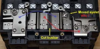
To make the parallel connections, I'll likely use some 10g (good for 55A chassis wiring) or 12g (good for 41A chassis wiring) wire and crimp ring terminals and just reuse the screw landing pads that the circuit board was connected to. Without the PCB in there, additional jumper wires will fit without any problem. I'll probably just cut off one of the "extra" eyelets and solder it to the busbar that I cut. Nickel plating should solder easy enough, I have plenty of silver solder and liquid flux from my audio projects - just need to be careful to avoid a cold solder joint with all of that metal mass.
The official specs from Toshiba are below. I'm assuming the 45c Ambient Temperature limit is in the context of the PCB and its tiny ICs than for the batteries themselves which seem to have a rating of 55-60c based on specs here and other specs I've found:
Spec table above comes from here:
https://www.global.toshiba/ww/products-solutions/battery/scib/product-next/product/module/2p12s.html
Here is an image of the label that is attached to the outer part of the case below the battery terminals. Seems that I'm about to violate the "terms and conditions" of use in multiple ways... Ooops... I hope I won't die as a result
😉
Below are some images of the PCB that I removed from the battery pack. The board is quite well made! All of the components are surface mounted and covered with a clear epoxy to provide some electrical insulation and vibration protection.
Toshiba seems to call this board the "Cell Monitoring Unit" which matches the silk screening along the bottom edge of the PCB. The official description of the battery pack is: "The battery module consists of 24 cells (2 in parallel and 12 in series), and incorporates the cell monitoring unit (CMU) that monitors the voltage and temperature of these cells."
Toshiba SCiB™ offers various components such as BMU, main connector, current sensor and electric leakage sensor.

www.global.toshiba
Another page has a slightly different description of a "Battery Management Unit" that is contained inside the battery pack: "Battery packs incorporate a BMU for monitoring cell voltage and temperature; overcharge, over-discharge, and over-temperature protection system; and a charge/discharge control."
Introducing the lineup of the SCiB™ Modules for automotive, public, industrial, power grid, building, facilities and railroad applications.
www.global.toshiba
I haven't yet found a separate high-current device that would provide the function of a "charger." I'm guessing one of those will be EXPENSIVE as these battery packs can be daisy-chained quite extensively: "You can construct a battery system by flexibly combining a single to tens of thousands of SCiB™ modules with other components according to your applications." I'm guessing at the level of "tens of thousands" of these battery packs, the application domain is a battery powered cargo ship or a commercial solar farm. I can't imagine that much battery weight in something that is on wheels. Making a 900v system (electric car) with these battery packs would require approx 33 units, at which point you're look at 1,000+ lbs of batteries.
The CMU/BMU board has a separate daughter board that accepts one 8-pin network cable as input and a second 8-pin network cable. These connections allow for integrating the control of multiple battery units. It's challenging to get a sharp image of the entire board all at once - I'm shooting on an angle in an effort to avoid reflections from my flash.
Bottom side:
Searching Model/Part numbers on the board only leads me to other people selling this same battery pack...
And a QR code that strangely links to a "Taylor Made Sur-Moor T3C Mooring Buoy, 12in Diameter." I can't find anything when searching on T3C1012, either...
Details for the network cable input/output board. It appears to be a simple I/O board - there are no components on it.
And another QR code - I'll have to remake this image, it's a little out of focus: