Mobius Super Capacitor.

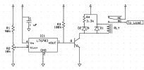
I sketched up a circuit that should do what you want. It uses a micro power voltage comparator with internal reference. This setup should draw less than 1 mA when idle. You can further lower this even further by increasing the resistor values though it may be more prone to electrical noise. The only only drawback is that the LT6703 comes only in non-DIY friendly form factor. The circuit can be connected either to always live (direct to battery) or switched power. The idea is that the relay is only energized when the feed voltage is greater than some value like 13.3 V (you can adjust using the potentiometer). That way, the camera will only power up when the motor is running.

View attachment 36001

I'll order parts and do a test build soon.

Is something like this already made by anyone? If not please show your parts with enough information that I/others can order the parts and get someone to build it, if you have the time. As I said before I wouldn't have the slightest idea how to start something like making this.
 
Not sure if any one offers this pre-built. Ant vendor browsing here, fell free to use this as inspiration for a product.

For you DIYers, all components are generic except the comparator, which is a Linear Technology LT6703-3:
https://www.mouser.com/ProductDetai...ayl/Ek2kXcXIDC2NbMwer7KvyawAPhZ5Hu9wOFpMALg==

The one I linked is in SOT-23 package. Throughole breakout are available for prototyping.

I'll order some and post the prototype when done here. I am planing to have the PCB professionally made later (components assembly will be done by me) for some other automotive project I have in mind. I have to work on the board layout though and that take some time even for such a low component count assembly because I have to get all the parts first in order to see how they fit.
 
@Radius8
Nice design, but missing the descriptors for the Transistor "Q". diode"D", and the relay. It would help others less familiar with schematics if you include where the relay contacts go to ;) I have some contacts on getting quality low-production circuit boards made but IIRC the minimum is 100 pcs. Let me know if you want me to dig deeper into that. Last question- are these going to be SMD? Some of us old folks have problems seeing those tiny buggers and may also not have the equipment to flow them into place. My smallest iron is 40W, far too big for the little stuff but fine for the older discrete components. I'd buy a few or more PCB's if you get a batch made. If they're SMD I'll get a friend to do the build :cool:

Phil
 
Thanks Radius8. I assume it's a SMD only?

I did come across a timer in one of the Amazon links (mentioned in the instructions for a different model) that claims no current drain. However, I haven't been able to find it for sale online. http://docs.timersshop.com/Multifunctional_TimerV5.pdf page 27 - referring only to the 10 Amp version of this timer https://www.amazon.com/gp/B00PD65UGA
With ignition OFF the timer has zero stand-by current consumption which is great for battery powered applications.

I also just came across this interesting design using the old faithful 555 timer https://makezine.com/projects/the-greenest-delay-timer/

Figure-A-Converted-Newest.png


A Zero Power Circuit
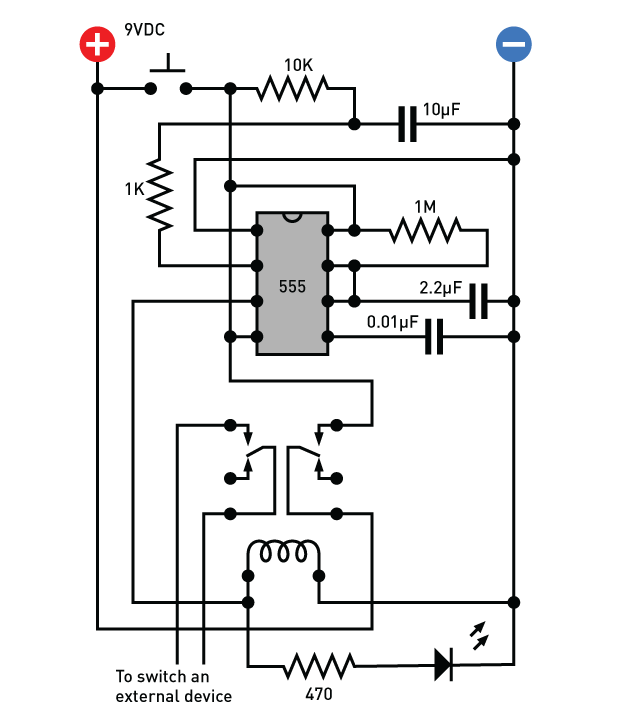
The circuit I came up with is unusual, but simple. When you press a button, it switches on a 555 timer chip, which activates a relay for a fixed interval. At the end of the interval, the relay switches off the timer, and the timer switches off the relay. Does that sound implausible? Take a look at the schematic in Figure A, which I have laid out so that it will be easily transferable to a breadboard.

When the button is pressed, it supplies power to pin 8 of the timer. Because the button is only switching on the timer, not triggering it, I had to add a 10µF capacitor to pass an initial low state through a 1K resistor to trigger the timer on pin 2, after which a 10K resistor maintains pin 2 at a high state.

The timer is wired in monostable (one-shot) mode, to emit a single delay pulse. The pulse goes out of pin 3 to the relay, which I have drawn to show its internal contacts. When the right-hand contacts close, they feed power back to pin 8 of the timer. So now the relay is powering the timer, and will continue to do so after the button is released, because the output pulse from the timer is still running the relay. The timer and the relay are sustaining each other — until the output pulse from the timer ends. Then the relay contacts open, which switches off the timer. At that point, we have zero power consumption, because the circuit between the positive bus and the negative bus is completely open.

Naturally you will need to adjust the output pulse of the timer to suit your application. For testing purposes, I have chosen component values for a pulse lasting slightly more than two seconds. For a longer pulse, just search online for a term such as “calculate 555 duration”, and you’ll find sites that tell you what component values to choose. I suggest you keep the 1M resistor and increase the value of the 2.2µF capacitor. A 56µF capacitor should create a pulse lasting about 1 minute. A 1,000µF capacitor should provide 18 minutes.

The left-hand contacts in the relay can be used to switch anything you like, within limits set by the manufacturer’s datasheet (typically, a couple of amps). A high-wattage light running on 115VAC would be acceptable.
 
@SawMaster, only the LT6703 is SMD (because it's not available in other packaging), all the others can be through hole "jelly bean". The relay is generic 12 V, the diode can be a 1N4001, the transistor also generic say something like 2N2222A. The only benefit of SMD would be size reduction but they are not emendable to modifications. For the relay, the center is to power and the normally open "NO" would go to the + of your camera power supply.

I have use expresspcb.com for my boards, not the cheapest probably but they make nice boards and have good turnaround time.
 
@murcod, I run a very simple 555 based timer in my daily driver which is connected to the switched power so it also uses no current when "off". Some derivative of circuit given in one of the famous Forrest Mims circuits book. Of course it's not as elegant as the voltage comparator.
 
Okay, a couple of hours nutting things out and I've come up with the below circuit using the dirt cheap timer from Ebay https://www.ebay.com.au/itm/332363552335 and four cheap and commonly available external components.

It uses no current when the ignition is off (once the time delay period has expired) - so no parasitic drain. :D

Excuse the "cut and shut" nature of the diagram.....

Delay%20off%20timer%20with%20nil%20parasitic%20current1.jpg


The diode type isn't critical (just use any rectifier diode), capacitor and resistor values aren't critical either. You want the capacitor large enough that it will pass sufficient current to latch the external relay "ON" before blocking DC current flow. The resistor in parallel is to discharge the capacitor when the IGN ON power is removed. The diode is to block any reverse voltage- without it I was having issues with the capacitor not discharging and holding the timer permanently on.

I've bench tested it on a 12V solar system (so basically the same voltages as in a vehicle) and it's been working perfectly. Use it at your own risk and don't forget to install a fuse in case something does go wrong!

The external relay I used it a generic 30A driving light type relay- overkill, but I had it lying around. Any 12VDC relay rated over 5Amps will be fine. (I've included the schematic for the horn/ driving light type relay for anybody wanting to use a different relay type.)
 
Last edited:
Okay, a couple of hours nutting things out and I've come up with the below circuit using the dirt cheap timer from Ebay https://www.ebay.com.au/itm/332363552335 and four cheap and commonly available external components.

It uses no current when the ignition is off (once the time delay period has expired) - so no parasitic drain. :D

Excuse the "cut and shut" nature of the diagram.....

Delay%20off%20timer%20with%20nil%20parasitic%20current1.jpg


The diode type isn't critical (just use any rectifier diode), capacitor and resistor values aren't critical either. You want the capacitor large enough that it will pass sufficient current to latch the external relay "ON" before blocking DC current flow. The resistor in parallel is to discharge the capacitor when the IGN ON power is removed. The diode is to block any reverse voltage- without it I was having issues with the capacitor not discharging and holding the timer permanently on.

I've bench tested it on a 12V solar system (so basically the same voltages as in a vehicle) and it's been working perfectly. Use it at your own risk and don't forget to install a fuse in case something does go wrong!

The external relay I used it a generic 30A driving light type relay- overkill, but I had it lying around. Any 12VDC relay rated over 5Amps will be fine. (I've included the schematic for the horn/ driving light type relay for anybody wanting to use a different relay type.)


Murcod Is this the timer you are referring to, just trying to help, totally out of my element here!
http://timers.shop/Multi-Functional-5V-20V-Time-Delay-Relay-Timer-5-amp_p_12.html
 
Last edited:
Murcod Is this the timer you are referring to, just trying to help, totally out of my element here!
http://timers.shop/Multi-Functional-5V-20V-Time-Delay-Relay-Timer-5-amp_p_12.html

No, using the module I linked from Ebay in that same post. The circuit could be adapted to any NE555 based timer circuit, but the diagram I drew has all the inputs and outputs labelled to match the linked Ebay module .

(I posted all that was required in the one post to avoid confusion! ;))

That module is very cheap and will give up to 25 seconds "power off" delay- more than enough to (hopefully) work around the limitations of the Mobius and ensure auto recording doesn't fail. Plus with the added components it won't flatten your car battery if you leave it parked for long periods.
 
Any ideas where nowadays you can buy a supercap for Mobius? Gearbest is not selling it anymore ...
Already have one, but another for spare would be a good idea :)
 
Any ideas where nowadays you can buy a supercap for Mobius? Gearbest is not selling it anymore ...
Already have one, but another for spare would be a good idea :)

Banggood used to sell them, don't see them there either. You could contact the manufacturer & supplier on eBay, they stock and sell it but for some reason don't have it listed.
 
Any ideas where nowadays you can buy a supercap for Mobius? Gearbest is not selling it anymore ...
Already have one, but another for spare would be a good idea :)

You can find many Mobius super-caps for sale on eBay. They tend to be priced on the high side but if you really want or need one you may find it may be worth the cost.

@Harsh's suggestion to contact eletoponline365 on eBay would be the first place to try but if they can't supply one at the moment there are at least some alternatives.

https://www.ebay.com/sch/i.html?_from=R40&_trksid=m570.l1313&_nkw=Mobius+super-capacitor&_sacat=0
 
Ok, let's see what eletoponline365 has to say. (y)
 
Last edited:
Just got in touch with eletoponline and he says that the supercap's not listed on ebay because is restricted for shipping (??) but can send one for 3.5 USD + 2.5 USD shipping cost.
 
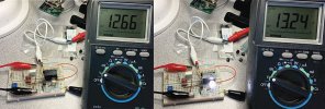
OK, I got my parts and successfully prototyped the voltage comparator circuit this weekend.

I set it so that the relay would trip when the supply voltage exceeds about 13.3 V (adjustable via the potentiometer). This way, the camera connected to the output of the relay will not be powered unless the engine is running, thereby preventing camera startup issues.

Circuit1_2.jpg

Here is the updated electrical diagram for those interested in building the circuit:
VoltageComparator2.jpg

The main IC is the LT6703HVHS5-3 (linked below) which is a micropower voltage comparator with internal reference. This one works within automotive voltage and temperature ranges. It comes in SMT SOT-23 (and even less friendly DNF package) so you'll have to get a breakout board.
LT6703 from Mouser
Breakout board for SOT-23

I used a good quality Panasonic 12 V relay with low coil current:
Relay

All other components are generic and widely available cheaply. I used what ever I had laying around. Of course, you can substitute any components, except for the LT6703 with equivalent ones of your choosing.

The R2 potentiometer was set at ~3K with respect to ground. By this I mean, get a 10k pot and set it with the center tap to 3k with respect to ground.
The D1 flyback diode can be a 1N4001
The transitor Q can be a 2N3904

The LED D2 and associated current limiting resistor are optional, and used only to indicate the status of the signal to the relay.

Adafruit sells some cute protoboards (various sizes) that could be useful:
Proto board
Also pick up some terminal blocks if needed:
Screw terminal blocks

I attempted to measure the current draw of this circuit at idle (not activated) and it was about 200 micro amp. I think this is well within tolerable limit :) to be able to even connect directly to always-live line if desired with minimal impact to your car battery. Obviously add in-line fuse to this. The circuit is relatively simple and does not have many parts but,
as always, build at your own risk. ;)
 
OK, I got my parts and successfully prototyped the voltage comparator circuit this weekend.

I set it so that the relay would trip when the supply voltage exceeds about 13.3 V (adjustable via the potentiometer). This way, the camera connected to the output of the relay will not be powered unless the engine is running, thereby preventing camera startup issues.

View attachment 36247

Here is the updated electrical diagram for those interested in building the circuit:
View attachment 36248

The main IC is the LT6703HVHS5-3 (linked below) which is a micropower voltage comparator with internal reference. This one works within automotive voltage and temperature ranges. It comes in SMT SOT-23 (and even less friendly DNF package) so you'll have to get a breakout board.
LT6703 from Mouser
Breakout board for SOT-23

I used a good quality Panasonic 12 V relay with low coil current:
Relay

All other components are generic and widely available cheaply. I used what ever I had laying around. Of course, you can substitute any components, except for the LT6703 with equivalent ones of your choosing.

The R2 potentiometer was set at ~3K with respect to ground. By this I mean, get a 10k pot and set it with the center tap to 3k with respect to ground.
The D1 flyback diode can be a 1N4001
The transitor Q can be a 2N3904

The LED D2 and associated current limiting resistor are optional, and used only to indicate the status of the signal to the relay.

Adafruit sells some cute protoboards (various sizes) that could be useful:
Proto board
Also pick up some terminal blocks if needed:
Screw terminal blocks

I attempted to measure the current draw of this circuit at idle (not activated) and it was about 200 micro amp. I think this is well within tolerable limit :) to be able to even connect directly to always-live line if desired with minimal impact to your car battery. Obviously add in-line fuse to this. The circuit is relatively simple and does not have many parts but,
as always, build at your own risk. ;)

Do you leave everything on the breadboard as a finished product for connection in your vehicle? This is all new to me.
 
Back
Top