A119 files still corrupting after capacitors changed

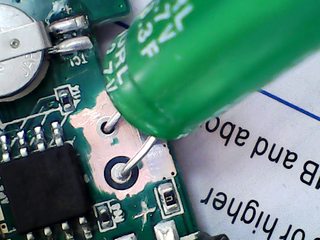
Ok I checked it again, from the the -ive and +ive of each legs, one capacitors gains 2.64v and other 0.62v, this is with the cam off but connected via USB
with the cam on one capacitor gains 2.67v and the other 0.02v. I am unsure why the power should even drop so much.
I am beginning to think the board could be damaged.

The voltage of near 5 volts was when I tested the positive of the USB supply and the negative of the capacitor without any capacitor connected

Last night I re-formatted the card and left it recording, seems to have only not recorded one file. I am going to try it in my car and see if it is the same.
 
The 2.67v is a good value. The other capacitor may have 1 leg not connected.

Can you check the voltages between 0 volts (maybe at the shell of the USB socket) and the legs of the good capacitor?
If the -leg is at around 0 volts then the other capacitor should have about +5v on its +leg and about 2.67v on its -leg.
If the -leg is at about 2.67v then the other capacitor should have 0 volts on its -leg and about +2.67 on its +leg.
Which leg has the wrong voltage?

Done the test with power button on and off whilst connected to a USB socket

power on
Capacitor 1: -ive = 3.21v, +ive = 4.11v
Capacitor 2: -ive = 0.05v, +ive = 0.05v

power off
Capacitor 1: -ive = 3.77v, +ive = 4.69v
Capacitor 2: -ive = 0v, +ive = 0v
 
  • Like
Reactions: gse
Seems like the second cap isn't making a good circuit connection to the PCB or maybe to upstream components (PCB trace failure). Can you check cap #2 again while powered up being sure you're getting a good connection to the PCB and not just the cap leg?

If you're not seeing several volts there doing this, follow the PCB traces to the next place you can get the probes to easily (do both sides of the cap) and check again. If still nothing then something's bad in the cap charging system. But if you do get the expected power this way, then you need to 'jump' the PCB traces from this test point to the caps with wire, which will bypass the damaged traces.

Phil
 
Done the test with power button on and off whilst connected to a USB socket

power on
Capacitor 1: -ive = 3.21v, +ive = 4.11v
Capacitor 2: -ive = 0.05v, +ive = 0.05v

power off
Capacitor 1: -ive = 3.77v, +ive = 4.69v
Capacitor 2: -ive = 0v, +ive = 0v
I assume that capacitor 1 is on the same side as the power socket?

If so, then the -leg of capacitor 1 should be connected to the +leg of capacitor 2. I assume that is not the case, you can check with a multimeter set for ohms, there should be almost no difference to the value with the probes touching each other. If they are not connected then you can make that connection with a short piece of wire, then it may start working, unless the +leg of capacitor 1 is not connected, I don't know where else that can be connected.
 
How did those soldering points get so damaged? Or do the pics make them look worse than they actually are?
 
How did those soldering points get so damaged? Or do the pics make them look worse than they actually are?
Most of that is just flux, some of it apparently burned flux, easy to make a PCB look bad when there is nothing wrong with it.

Safer to bypass the problem than try to clean it up though, and even safer to avoid the problem in the first place by soldering to the old legs, even though that will never look good.
 
That to me looks like the solder area has been burnt? I hope that the OP cleaned the area before soldering the caps back in.

Why doesn’t the OP clean up the are and then take some pics, we might then be able to determine if tracks have been lifted and where to possibly solder to to remedy the possible lifted track(s).
 
Seems like the second cap isn't making a good circuit connection to the PCB or maybe to upstream components (PCB trace failure). Can you check cap #2 again while powered up being sure you're getting a good connection to the PCB and not just the cap leg?

If you're not seeing several volts there doing this, follow the PCB traces to the next place you can get the probes to easily (do both sides of the cap) and check again. If still nothing then something's bad in the cap charging system. But if you do get the expected power this way, then you need to 'jump' the PCB traces from this test point to the caps with wire, which will bypass the damaged traces.

Phil
I checked the cap both sides of the boards and nothing. I have even just removed them again completely from the board and same thing. I have tried tracing it back further and no cigar. One leg goes to the integrated circuit chip IIRC

I assume that capacitor 1 is on the same side as the power socket?

If so, then the -leg of capacitor 1 should be connected to the +leg of capacitor 2. I assume that is not the case, you can check with a multimeter set for ohms, there should be almost no difference to the value with the probes touching each other. If they are not connected then you can make that connection with a short piece of wire, then it may start working, unless the +leg of capacitor 1 is not connected, I don't know where else that can be connected.
Capacitor 1 is indeed the same side of the USB power socket, the one beside the little battery.

That to me looks like the solder area has been burnt? I hope that the OP cleaned the area before soldering the caps back in.

Why doesn’t the OP clean up the are and then take some pics, we might then be able to determine if tracks have been lifted and where to possibly solder to to remedy the possible lifted track(s).
I did clean it up better than the first pic, I didn't take a pic after that. I have just removed the capacitors again and taken a pic, cleaned it again, but not as much as the second time I did.
DSCF1979.JPGDSCF1980.JPG
 
If you're getting nothing on the traces going to the second cap then you're probably got a bad component somewhere else in the circuit. The water gets deep at tht point unless you have a good magnifier, a good DMM, and know how to identify and test components in-circuit. If it's a programmed chip there's no fix. Not DIY stuff unless you're already there. When components were big enough to see I did some circuit tracing and repairs but with SMD I don't bother anymore. I just can't work with things that small. YMMV.

Phil
 
I checked the cap both sides of the boards and nothing. I have even just removed them again completely from the board and same thing. I have tried tracing it back further and no cigar. One leg goes to the integrated circuit chip IIRC

Hi @Vincy Gav I've been following your thread and became interested in it.

The board is multi layer.
The second cap does not have a visible path to anything.
It is connected via another layer between the top and bottom layer. The board is most likely a 4 layer board.
The internal layers rely heavily on the sleeve that runs from the top to the bottom of the board in this case the capacitor. It also uses Vias. If the selves are damaged then there is no connection to the inner layers.

The capacitors are joined in series therefore they add up to a total value of 1.65 Farad. The voltage across each cap will be ~2.5V *note not measured but calculated.

The capacitor nearest the battery positive terminal is directly connected to the negative terminal of the capacitor nearest the microphone.

Looking at your cct board I think you may have other issues as the holes for the capacitors look damaged. Some of the tracks may also be broken.

Photos showing the tracks with the green removed.

Hope that helps out.

EG8vZITm.png
00pX3fym.png
w4kOH2Im.png
yOb6ierm.png


CamDmckm.jpg
RIStNqGl.jpg
 
I hadn't considered the possibility of a multi-layer board. The most I've seen in other dashcams were two-sided. Not having one of these cam's to look at I can't say.

If the caps are charged in series then it would be strange to have one cap charge while the other one didn't unless one cap was bad (internal short or excess resistance). Now I'm wondering if that's the problem.

Phil
 
Then it would have vias and that's likely the problem. Time for a new cam then :(

Phil
 
I still can’t believe how wrecked the board is, to the OP what tools did you use, specifically what soldering iron?
 
@IAmATeaf Discussed earlier in this thread. Have to give credit to them for trying which is a lot more than most cam owners would do. My own skills (and tools) have become quite rusty from a lack of use since the advent of SMD designs as I just can see what I'm doing very well anymore, especially with things this tiny :cry:

Phil
 
blowtorch maybe ???

It does look like damage from a heat gun, not enough focused heat and then the caps being pulled before the solder started to flow which caused the tracked to be ripped off.
 
Hi @Vincy Gav I've been following your thread and became interested in it.

The board is multi layer.
The second cap does not have a visible path to anything.
It is connected via another layer between the top and bottom layer. The board is most likely a 4 layer board.
The internal layers rely heavily on the sleeve that runs from the top to the bottom of the board in this case the capacitor. It also uses Vias. If the selves are damaged then there is no connection to the inner layers.

The capacitors are joined in series therefore they add up to a total value of 1.65 Farad. The voltage across each cap will be ~2.5V *note not measured but calculated.

The capacitor nearest the battery positive terminal is directly connected to the negative terminal of the capacitor nearest the microphone.

Looking at your cct board I think you may have other issues as the holes for the capacitors look damaged. Some of the tracks may also be broken.

Photos showing the tracks with the green removed.

Hope that helps out.

EG8vZITm.png
00pX3fym.png
w4kOH2Im.png
yOb6ierm.png


CamDmckm.jpg
RIStNqGl.jpg
I realised after that it was dual layer,but didn't realise it was multi layer.
I hadn't considered the possibility of a multi-layer board. The most I've seen in other dashcams were two-sided. Not having one of these cam's to look at I can't say.

If the caps are charged in series then it would be strange to have one cap charge while the other one didn't unless one cap was bad (internal short or excess resistance). Now I'm wondering if that's the problem.

Phil
I am beginning to think this was already part of the problem prior to me originally removing the caps. I only wish I checked the voltage of the old ones prior to removing them to prove this. I never thought of the cap going bad.

I still can’t believe how wrecked the board is, to the OP what tools did you use, specifically what soldering iron?
I used a dekton 30w soldering iron. Well the picture I have taken above is after removing and re-soldering for the 5th time. I have soldered many things in the past successfully, even with capacitors and not had any problems until now. The soldering tip I should have changed, had it for years, its a bit blunt, instead of being sharp.
I may just throw it in the bin now, had enough.
 
I may just throw it in the bin now, had enough.
Have you tried connecting the two capacitors via a wire, as I suggested above? The diagnostics suggested this has a reasonable chance of working...
 
Back
Top