HK3-H hardware kit arrives! (Viofo is not going to be happy about it)

Thank you for your feedback and input guys! Below I'll try to comment on some of the points:


Thanks for heads-up! I was planning on setting it to 60 seconds but this will be an easy programming fix if I need to make the delay longer or shorter for any reason. Actually planning on having own logic for that and make the device to repeatedly measure battery voltage multiple times over the delay countdown to make sure it is a true low-voltage situation.


It is pretty much a complete disconnect from the battery until next time the car starts! The quiescent current will be in the range of 25uA which is smaller than battery self discharge rate.


I am able to monitor and log both, however I've opted out from current monitoring for now as I pretty much know what it is.
By the way, I'm pretty big nerd when it comes to data-logging (even recording radiation levels from my balcony lol).


It is integrated inside of the buck module. Part of the requirements that I've set for myself was to find a DC converter with integrated inductor, so that all the inductance and EMI stuff is taken care of by the manufacturer of the IC chip.


Right now the BOM is around 15$ with the DC chip costing almost 2/3 of the total BOM (since it is a military grade part). It can be swapped for a less expensive industrial/automotive grade parts or parts in different packaging.


I did not, I've run some tests on different components of the design as well as some electrical simulations, but part of the design relies on the very specific resistor/capacitors values which would be hard to adopt to breadboard format (and quiet frankly expensive), so it made sense for me to just straight up design and order the PCB - after all its not that expensive anymore. Most of the parts will be assembled via SMT assembly with the exception of the DC chip.


Thank you sir! You are correct, there is a UART interface as well as ISP (can use both for programming and data logging). The DTR pin is for the onboard programming of the atmega328p via ISP but you are right, I have an ESP32 based hub sitting at home that has LoRa and NRF24 radio modules to receive the signal. Since after initial programming of the module, ISP pins will no longer be needed, I can attach NRF24L01 module to those or if the range won't be good enough, can swap it for a LoRa module and then the whole neighborhood will be able to receive my car's battery status, lol.

To be honest, I'm still undecided whether I want to add wireless capabilities since I already have more than enough of such devices around the house, but I agree with you that with proper implementation it opens up a world of analytics on the car battery.


Thank you for the feedback! The cut-off voltages can be set to anything as it is a programmable value. Realistically I only need one since this will be the testing prototype for myself, but there is a program button already in the design that via some basic LED blinking interface can allow for selecting a value from the pre-programmed range.
Please make something that we can go below 11.8v. Sometimes my battery pack is 50% + and my dashcam shuts off in parking mode because the battery pack is a little cold and drops below 11.8v.
 
This is quite interesting, a while back I was playing with a Multisafer VU and had the thought of designing my own parking mode controller:


Since then I've looked into it a bit (hardware required etc) but no further than that.

Will be interesting reading further updates with this(y)
 
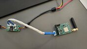
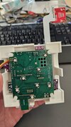
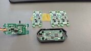
Just got my first batch delivered! Some soldering and a weekend of testing is ahead! Perfect fit for the existing housing as well! :) The original board for the reference is on the left!

20230217_141712.jpg
 
Well guys, I promised you updates even if the whole thing cached on fire! So here comes one fresh from the oven!

I've soldered everything together and hooked it up to a 12v power supply. Pressed the on button on the outlet... nothing popped, nor released any magic smoke - no fire!! That was a relief!

I then started probing for voltages on the board and while on the input side I saw 12v as expected, I did not see any 5v on the output.... $h!t!

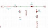
Started digging through the schematics and simulations and at the same time probing voltages on logical side of the board and found out there is no "high" signal on the regulator Enable pin - it was only getting 1v instead of expected 4.5v. The ACC was supposed to be converted from 12 v to ~5v via resistor divider circuit, however for some reason, the output of that circuit was showing only 1V. Looked back at the related part on the schematics and ...$h!t(again)! Those of you who have worked on designing logic circuits may have already guessed my mistake on the schema below.

issue point.JPG

Although the resistor divider circuit is OK on its own, there is 1 more line attached to it for which I did not bother putting much though. And that was my mistake! That A1_Sens connection goes directly to the Atmega (which would read whether ACC is High or LOW), however I have completely forgot that when atmega is not powered up and configured, its pins will actually sink the current. So effectively that 33k resistor to ground was replaced with almost a direct line to ground - thus no 5v as expected.

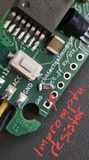
So I needed to come up with a fix - cut the traces on the PCB and micro-soldered an impromptu 220k resistor on that A1_sens line. Luckily I had a very convenient trace jump for this line!

20230217_183859.jpg


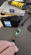
After hooking up everything for the second time, pressing the power button and reading output voltages, I got a great relief! I saw 5.08v on the output! Hooked up the camera itself and all worked like a charm! One thing I have to comment on - I don't know why so many people praise Viofo for the original kits, from what I have seen - Viofo put the bare minimum to create the HK3 kit and cut corners everywhere they could (not even talking about shady ICs and hang-up issues). The wiring that goes from the board to the camera is made of 24AWG wire! Viofo could have charged us extra 50 cents and put more robust 22AWG (original that comes with the A129 pro is a proper 22AWG cable and I just cant comprehend why cut corners on such things?)

Anyways, coming back to my project, at the camera end, the voltage drops to 4.9v (which is all due to losses on 24AWG wire)
As for the regulator and the board temperatures - the regulator barely got any warm (my estimate is that temperature rises to about 40-45C as it can be barely felt with a touch). I wish I had a FLIR camera so that I could check what parts of the board heat the most, but from touching it all around, only the DC chip is slightly warmer than the ambient temps. I also wish I had an oscilloscope to test the voltage ripple - if anyone has a good advise on how to measure it on a budget, I would greatly appreciate it!
Next step is to receive my bench power supply and start testing the whole thing with a little bit more abuse :) and of course all the software fun (I have decided to hook it up to a LoRa module to gather some live data)! Oh, and the final photo of everything working together:

20230217_180902.jpg

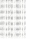
And some temps reading for over an hour with the whole board wrapped in electrical tape so it accumulates heat (imitating enclosure space):

temps.JPG
 
Last edited:
Update #3:

Unfortunately this one is without any photos or screenshots. Finally got my lab power supply and was able to do some experimenting with different voltages as well as adding extra resistive load to the circuit. The only final test that I could not perform in its entirety was reading voltage ripple at the output of the buck converter as well as at the camera end (however I did some high level experimenting).

Here are some power stats of A129 PRO (running at 1440p/30fps) via HK3-Homebrew supplied with 12.5v:

ACC ON: ~ 265mA / 3.3W
ACC OFF (3fps time-lapse parking mode ): 215ma / 2.7W

Maximum temperature of the buck module ever recorder with extra 100mA resistive load (literally bunch of resistors shorted at around ~60ohm) was under 42C. Normal running at room temperature is 38-39C, so there is a lot of headroom on the heat front.

There was no significant difference in power consumption or temperatures when I powered the module with 12v vs 14.5v (max expected on my car).

Low voltage shutdown works flawlessly! The difference between actual voltage at the input of the module and the module calculated is under 5mv. After the disconnect, the whole circuit consumes only around 20uA (25uA is expected per DC module datasheet). What is interesting is that the wire supplied with HK3 kit that runs from battery to the DC module itself causes 5mv drop (so the total difference between the reading and the supply end is close to 7-10mv - totally ok with me as a buffer).

Now for the grey are - ripple voltage. Obviously the answer would come if I had an oscilloscope at hand, but since I don't have one, I had to improvise! I've tried measuring the output ripple voltage a few different ways and at the different ends and got very similar results. One method was using digital voltage/current IC same to the one used in my module and polling it at its highest frequency. The second approach was using a digital multimeter set in AC mode. Both showed very similar results! At the output end of the module, ripple voltage was around 20mV, however at the output end of the wire that leads to the dashcam (well in fact GPS contacts of the camera, so wire + dashcam) the ripple reading was between 100 and 200mV. I have also observed that "ripple" is a lot lower when the dashcam screen is on! Apparently the wire plays a big role in this, but this also can be caused by the type of voltage regulation used inside of A129 Pro. I thought A129 uses linear regulator, but now not so sure about it. If anyone has any insight on A129 Pro internals - this would be highly appreciated!

Next steps are setting up LoRa transceiver and testing telemetry range (I kind of did this already with other devices and expecting 200-300m range) and installing everything in the car.

Below is the sample data I'm reading from the module right at this moment:

22:27:00.047 -> Temp: 37.75 TempMax: 38.63 TempMin: 33.69 BatV: 12.42 BatVMax: 14.45 BatVMin: 12.31

With exception of forgetting about that one resistor mentioned in the post above, I believe this project is a success :)! (I've also found a way to use more accessible and cheaper parts, but at the moment don't really see a financial incentive to pursue the whole thing as commercial project unless someone wants to collaborate).

Is it possible that you have reduced the power used by the dashcam with Hard wire kit? In some testing I did ages ago I found the HK used a fair amount of current, cant remember exactly but 70mA?

A crude way testing ripple would be to run the dashcam normally using you unit and then checking the screen and the resultant recordings to see if there is any interference. Its not an eloquent method but you are just wanting a result that works really.

With the temperature would this be an issue in a hot climate? At my place it is currently 30c and I know my car will be a lot hotter.

Congratulations on completing the project and now moving on to the nice to haves. Cool!
 
Is it possible that you have reduced the power used by the dashcam with Hard wire kit?
The efficiency is probably a lot better then the original kit, but at the same time the module runs very inefficiently for its capabilities. Hard to explain, but this thing is very overengineered for what it needs to be and currently runs at probably at 10-20% of its capabilities. My main goal was keeping temps to the minimum, and I've definitely achieved that. Once I'm done with this project, I'll put the original kit to the same test, but expecting 50c+ temps with higher power consumption.

A crude way testing ripple would be to run the dashcam normally using you unit and then checking the screen and the resultant recordings to see if there is any interference. Its not an eloquent method but you are just wanting a result that works really.
I'm looking at a lot more scientific approach :) Dashcam itself runs flawlessly. I'm just curious to see whether my design fits DC IC module datasheet characteristics, and for that I need a scope that can read at least a mhz (obviously a lot more). For a final product I have no doubt it is x times better then the original kit ripple. Datasheet promised 20mV which is kind of what I've seen on the board output based on my elaborate testing approach - for reference, there were reports on this forum that HK3 had over few Volts ripple - that is 1000x worse then my results (those modules may have been very very faulty though).

With the temperature would this be an issue in a hot climate?
Nope, It runs waaaay cooler then the original kit - heat was my main concern in designing this. The DC circuit is rated up to 85C before it starts loosing its characteristics. I also live in a hot climate so heat was my number 1 concern to tackle (thus all the overengineering).

Congratulations on completing the project and now moving on to the nice to haves. Cool!
Thank you sir! Although I kind of feel sad as I now need to find something new to occupy myself with, lol.

I'll post another update once everything is integrated in the car and I am able to receive telemetry (at some point considered LoRaWAN network that can send data to my home regardless of where the car is, but letting it go as this project is getting out of hand now lol)
 
The efficiency is probably a lot better then the original kit, but at the same time the module runs very inefficiently for its capabilities. Hard to explain, but this thing is very overengineered for what it needs to be and currently runs at probably at 10-20% of its capabilities. My main goal was keeping temps to the minimum, and I've definitely achieved that. Once I'm done with this project, I'll put the original kit to the same test, but expecting 50c+ temps with higher power consumption.


I'm looking at a lot more scientific approach :) Dashcam itself runs flawlessly. I'm just curious to see whether my design fits DC IC module datasheet characteristics, and for that I need a scope that can read at least a mhz (obviously a lot more). For a final product I have no doubt it is x times better then the original kit ripple. Datasheet promised 20mV which is kind of what I've seen on the board output based on my elaborate testing approach - for reference, there were reports on this forum that HK3 had over few Volts ripple - that is 1000x worse then my results (those modules may have been very very faulty though).


Nope, It runs waaaay cooler then the original kit - heat was my main concern in designing this. The DC circuit is rated up to 85C before it starts loosing its characteristics. I also live in a hot climate so heat was my number 1 concern to tackle (thus all the overengineering).


Thank you sir! Although I kind of feel sad as I now need to find something new to occupy myself with, lol.

I'll post another update once everything is integrated in the car and I am able to receive telemetry (at some point considered LoRaWAN network that can send data to my home regardless of where the car is, but letting it go as this project is getting out of hand now lol)
Looking forward to updates.
I looked up LoRaWAN nice solution for telemetry.
I read its maximum data rate is 50Kbs which unfortunately wouldn't suit video unless your really patient a 3GB file would only take 5.5 days! :geek:
 
Looking forward to updates.
I looked up LoRaWAN nice solution for telemetry.
I read its maximum data rate is 50Kbs which unfortunately wouldn't suit video unless your really patient a 3GB file would only take 5.5 days! :geek:
LoRaWan is for sensor data transmission, not video. And to transmit video from the cam, I'd need to tinker with the camera itself lol, which I don't want to do (after all, don't really see a need for it). So for now it's just data transmission from the hardwire kit. I've already put everything together and tested it, got about a km of range with direct line of sight and about 300m through concrete walls of the parking lot. Unfortunately busy this weekend so can't do the final assembly, but for sure will keep you guys posted. Have 2 more updates to do I guess. One with the final set up, and one with data observed from the car with car battery discharge graphs.
 
Small update: The HK4 kit i ordered arrived, after measuring the different signals on the breakout bord it seems to be the A5/B5 (which one depends on the orientation of the plug) signal that is 4.95V if the switched 12V is present and 0 if not (permanent VCC is 5.45V) . So If anyone ever wants to adapt this for a usb C version , this is the pin to use. Note: I did not crack open the black box to make 100% sure that these are the only things connected since I don't want to void the warranty yet as I see on the QC sticker it was produced in 04/2022 so likely with crappy corona substitute components and likely to fail.
 
Small update: The HK4 kit i ordered arrived, after measuring the different signals on the breakout bord it seems to be the A5/B5 (which one depends on the orientation of the plug) signal that is 4.95V if the switched 12V is present and 0 if not (permanent VCC is 5.45V) . So If anyone ever wants to adapt this for a usb C version , this is the pin to use. Note: I did not crack open the black box to make 100% sure that these are the only things connected since I don't want to void the warranty yet as I see on the QC sticker it was produced in 04/2022 so likely with crappy corona substitute components and likely to fail.
I think your module should be fine. I have not seen any reports of faulty hk kits with USB Type C. Overall big part of the kit is the cable that goes to the camera. It's pretty much impossible to purchase a ready to go one, at least for mini B version as they utilize USB ID pin on the mini B which is not wired in 99% of USB cables. So to recreate such a project one would still need to purchase the kit and then install custom board on it.
 
I would expect the pcb/components of the usb C version to be exactly the same as the version you had ? Why would they make different variants of that part ? It still needs to make a permanent 5V and a switched one ?
Anyway once the warranty is expired I will have a look :p (not sure if that is 3 months or 1 year since I am in Europe).
And lol, USB is a great standard isn't it :D. I spend a few hours last week searching for an USB C to C cable for a different project which has all the cables present, meaning also the SBU kabels. Seems you can get lucky with the 10 GBps certified ones. Of course several times more expensive than the ones with only a limited number of signals connected.
Well, the USB C version of the hardware kit came out a lot later than the original kit. Besides the new dashcams with 3 video sources can potentially be a bit more power hungry, so I'd assume they would do some improvements to the power circuit since the original kit. Anyways, viofo uses "proprietary" although very simple USB protocol to communicate between the hardwire kit and the camera and you simply can't use any USB cable to create your own hardwiring kit.

But yes, totally agree with you, on the marketing side USB C was supposed to be the gold standard of all, in reality it's crazy how much of a variability there is in terms of connectivity and driving power on these. But I can somewhat understand it, not every application needs 6 or more data channels, thus all the complexity and inconsistency around it.

P.S. My board can drive up to 5 of the newest cams, but it will heat up beyond the comfort zone for me personally)
 
Update #4:

So I finally got some time to finalize the project, including setting up LoRa TX board as well as writing code for the 2 boards. At this stage everything works as planned and all the targets I've set are achieved.

So what do I have now!?

A fully functional HK3 kit replacement with programmable voltage cut-off and wireless data transmission. I currently have 5 programs for Vcut-off ranging between 12v and 12.4 (but can set as many programs as needed) - the interaction for choosing a program works as follows:

Long press Prog button for 5 seconds - the LED starts blinking rapidly (indicating entering program mode), after which blinks slowly to indicate which program I'm currently in (3 blinks for 12.2v setting for example).
Short press Prog button (while in programming mode) and it will iterate through the programs, going to the next one and blinking x-times accordingly.
Leave the module for 2 minutes and it will exit the programming mode, storing current setting in the long-term memory as default.

Every minute the module will send data via LoRa on all the stats such as current battery voltage, max and min voltage recorded during the operation of the module (after last Low-voltage cut-off), all the temperature sensors data (I have 2, one inside and one outside of the board on LoRa module). It will also record and transmit data on whether the car is running or not as well as when the HK is about to shut down because of low battery and some debug data in case if there are any issues.

The final set-up without enclosure looks like this:

HK3-H + LoRa TX module:
20230303_174423.jpg

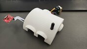
My smart home hub that receives over 50 different data points and forwards those to a web server (it is pretty now after a 3D printed enclosure in a form of Igloo, lol):
20230303_175013.jpg
20230303_175031.jpg


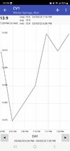
... And the data I can see on my phone! The chart is showing current Voltage reading from a lab power supply:
Screenshot_20230303_192932_Public Monitoring 2019.jpg


Next step will be covering both boards in conformal coating and installing everything in the car. I am curious to see how long the car battery will last running in parking mode on a typical day. I am planning to post usage statistics in my last update so it might take some time before you guys see update #5 but in the mean time if you have questions or comments, would be glad to respond!
 
Hi, this is really cool and I like all the extras that you've added, nice job!

If your replacement puts less drain on the 12v battery compared to the original then even better.
 
Hi, this is really cool and I like all the extras that you've added, nice job!

If your replacement puts less drain on the 12v battery compared to the original then even better.
Hey, Thanks!

The replacement is a bit more power efficient but should run a lot cooler then the original. Overall the consumption is still high even in Park mode as the main consumer is the Camera itself, not the HK kit.

I will be posting how much a typical car battery can last before the V-cut-off once I get it installed in the car (was actually planning on doing it today but got a flat tire because of running over a nail so was busy with fixing that lol).
 
I have a Viofo A129a Pro duo, in my 2014.4 Camry Hybrid. The Hybrid 12V Battery is AGM. the Hardwire power kit that runs the 12v to the dash cam drains my battery if it is parked more than 4 days. I then have to put a charger on my 12V battery to start the car. The A129a pro duo is a power hog. I don't see a reason to try anew kit, if it will still be a 12v power draw issue with the dash cam. I could just pull the plug on the camera while it sits in out garage for a week without driving, but this is insane. They cables to the camera are not made well and could not withstand the plugging and unplugging many times. I have already had to replace one of the cable for causing issues. My camera is only about 2.5 years old.
 
Is it possible that you have reduced the power used by the dashcam with Hard wire kit? In some testing I did ages ago I found the HK used a fair amount of current, cant remember exactly but 70mA?

A crude way testing ripple would be to run the dashcam normally using you unit and then checking the screen and the resultant recordings to see if there is any interference. Its not an eloquent method but you are just wanting a result that works really.

With the temperature would this be an issue in a hot climate? At my place it is currently 30c and I know my car will be a lot hotter.

Congratulations on completing the project and now moving on to the nice to haves. Cool!
if someone took a proto board pcb and put in a couple zener diodes and whatever resistors, to cut the power the dashcam from the battery, if the battery dropped to say 12.4 v to keep the car's 12v battery from dropping below require voltage to run the car. I don't need all of these other power hungry circuits people are making.
 
The A129a pro duo is a power hog. I don't see a reason to try anew kit, if it will still be a 12v power draw issue with the dash cam.

Your car fan will be a bigger power hog but we don't complain about it as we need it when we need it and that's ok.
Same with the Dashcam.

However if the charge circuit is not working correctly OR the car is still on with engine off then it will drain the battery. Not too sure about the hybrid tbh.

This thread is about some dude called @bobcat who wanted to make his own cct and has nothing to do with any Dashcam maker.

Personally I'm very interested in his efforts as it has been a problem for some Dashcam owners to have a Hardwire kit that doesn't work correctly eg flattens the car battery. Do a search and you will find various discussion on the subject.


proto board pcb and put in a couple zener diodes and whatever resistors, to cut the power the dashcam

You worried about the Dashcam being a power hog and you suggest zenors.

I know you know there is a loss and heat with that type of circuit. Not very efficient compared to todays latest technologies.

A reply to just shut the power off when the ignition is off is a part solution.
Types of power regulation:
Using a FET cct is one solution and a voltage regulator another.
Switched mode another.

Micro processor another.

Hope that helps clarify a couple of things.

Cheers
Corrected some spelling/words (bloody predictive text is my excuse and I'm sticking with that)
 
Last edited:
Back
Top