HK3-H hardware kit arrives! (Viofo is not going to be happy about it)

if someone took a proto board pcb and put in a couple zener diodes and whatever resistors, to cut the power the dashcam from the battery, if the battery dropped to say 12.4 v to keep the car's 12v battery from dropping below require voltage to run the car. I don't need all of these other power hungry circuits people are making.
The level of entitlement in this one is beyond my comprehension.

You sir, sound like I've been knocking on your door the whole morning, trying to sell you this product, when in reality:

a) You have no idea what my project is about and how it works (reading page 1 is a good starting point)
b) You have no idea what HK kit does in general and how voltage conversion works in them - I would have not pointed this out if you did not make a very false statement (hint: these circuits don't drain power and are extremely efficient!)
c) Go ahead and make something out of a couple of zeners and resistors (honestly I have no idea what you could make out of those and what does "cut the power" to dashcam mean!?), but at a minimum, you'd burn those zeners (I don't want to think what would happen to your car).
d) if your camera worked for 4 days straight hardwired to battery:
d.1) That's darn great! Your car has a nice battery capacity!
d.2) You messed up HK installation, since the ACC Low-voltage Cut-off did not trigger - most likely your ACC wired to something other then "power on ignition" source.
 
Last edited:
Update #5.

I guess my final major update on the project! I was able to install everything in my car last Friday and have been recording telemetry since then. Unfortunately I did not take any photos of the installation as it was very hot outside and I just wanted to get done with it ASAP.

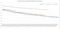
The car has a 5 year old battery in it with a pretty small capacity and so far I was not able to trigger a Low voltage cut-off, as I drive the car daily. I estimate that on a good battery charge the parking mode should last between 20 to 30 hours based on the discharge curves I've observed. The telemetry reception is extremely reliable even when the whole thing is tucked next to a metal body frame with dozens of wires running around it. Maximum temperature observed so far was 55C and typically HK kit runs about 10-15c higher than the ambient. Mind you that 55C was recorded when the ambient was close to 45C - was cleaning my car out in the direct sunlight on the compartment where everything is hidden.

Below are the discharge rates with 2 curves for the dashcam operating in Parking Mode (5 or 3 fps time-lapse, don't remember the exact setting but it does not matter) and the grey curve is when the camera was disconnected, monitoring the self-discharge rate of the car's battery.

Hk2.JPG

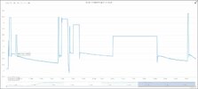
and here is what a typical chart looks like for a few days of records on the car battery voltages.
Long flat areas are from when I was away from my house (start the car - voltage jumps up > drive away - voltage stays the same as the home station is no longer receiving updated values until I'm back home). You can tell I was not at home all Sunday long, lol.


HK1.JPG
 
Last edited:
Update #5.

I guess my final major update on the project! I was able to install everything in my car last Friday and have been recording telemetry since then. Unfortunately I did not take any photos of the installation as it was very hot outside and I just wanted to get done with it ASAP.

The car has a 5 year old battery in it with a pretty small capacity and so far I was not able to trigger a Low voltage cut-off, as I drive the car daily. I estimate that on a good battery charge the parking mode should last between 20 to 30 hours based on the discharge curves I've observed. The telemetry reception is extremely reliable even when the whole thing is tucked next to a metal body frame with dozens of wires running around it. Maximum temperature observed so far was 55C and typically HK kit runs about 10-15c higher than the ambient. Mind you that 55C was recorded when the ambient was close to 45C - was cleaning my car out in the direct sunlight on the compartment where everything is hidden.

Below are the discharge rates with 2 curves for the dashcam operating in Parking Mode (5 or 3 fps time-lapse, don't remember the exact setting but it does not matter) and the grey curve is when the camera was disconnected, monitoring the self-discharge rate of the car's battery.

View attachment 64466

and here is what a typical chart looks like for a few days of records on the car battery voltages.
Long flat areas are from when I was away from my house (start the car - voltage jumps up > drive away - voltage stays the same as the home station is no longer receiving updated values until I'm back home). You can tell I was not at home all Sunday long, lol.


View attachment 64467

Amazing job.

Thank you sir! Although I kind of feel sad as I now need to find something new to occupy myself with, lol.

Well the obvious first thing is when are you going to send me one or something

I'm very interested in the programming and electronics of your unit.

The other thing you may have already considered is producing these or at least get someone to make them under licence to you.

I have another addition you may consider is a temperature sensor in the Dashcam.
I know wiring would be an extra pain but I offer this solution:
Send a signal down the positive line.
A DS18B20 is a one wire device (needs power also)
Then using the logging system introduce some memory so it can also store the logs while away from your house.

Your welcome to pm me.

Thanks for keeping the forum (me really) updated.
Cheers.

 
Thank you for the support @LateralNW! It was certainly an interesting project for me and I appreciate that some of you guys expressed interest as well!

Well the obvious first thing is when are you going to send me one or something

Lol, I honestly would send you one if I did not have that one screw-up with a missing resistor. The other problem is that the main DC-DC IC is out of stock everywhere and I don't have any spares left. What I can probably do is send you manufacturing files with a corrected PCB as well as BOM so that you can order the boards yourself from JLCPCB, as long as you can source the DC chip and solder in a few components on the top side of the board. (well in reality there is a bit more to it as you also need to be able to program the board with the software I've written which requires a bit of knowledge on USBISP programming)

I've already found another IC that I could use, which is easy to source but will require an external inductor, but also does require some changes in schematic and the PCB design - not sure if I'm ready for a redesign as I don't have a need for one.

The other thing you may have already considered is producing these or at least get someone to make them under licence to you.

I've done some research and such a device simply would not be profitable to sell, given all the competition and pricing (it will probably cost double to manufacture comparing to the existing kits). I am certainly open to discussion if any of the manufacturers are interested.

I have another addition you may consider is a temperature sensor in the Dashcam.
I know wiring would be an extra pain but I offer this solution:
Send a signal down the positive line.
A DS18B20 is a one wire device (needs power also)
Then using the logging system introduce some memory so it can also store the logs while away from your house.

Actually both of the temperature sensors I've used are DS18b20 PAR. They are extremely reliable and simple to operate as long as those chips are not fakes, but it would not be easy to install one on the camera itself as it will require an additional data line (I could use the ACC signal wire when it is not in use (car is off), but at the same time camera is in its coolest state when in parking mode, so it defeats the purpose). To be honest, I don't even want to know how hot the camera can get lol, relying on Viofo's overheat protection on this one.

What is interesting is that A129Pro gets extremely hot in drive mode and moderately warm while in park mode, but there is no significant difference in power consumption between the two modes, only like 0.5W or so but apparently that extra power does produce a lot more heat.

I'm very interested in the programming and electronics of your unit.
All is written in Arduino IDE, there are 2 codes, one for the DC converter unit and the other is for optional LoRa module. Each of those has about 250-300 lines of code. Some old-school engineers will say that Arduino IDE is a sandbox and is not suitable for serious applications, but I strongly disagree with that, I have a few devices running perfectly for almost a decade under pretty extreme conditions and the atmega chips programmed with Arduino never failed.
 
Last edited:
Hi, out of interest, what software do you use to build/test the circuits, and to create the board file?
 
Hi, out of interest, what software do you use to build/test the circuits, and to create the board file?
I used KiCad 6 for the pcb design and production files and Falstad circuit simulator to test some of the elements of the circuit. Usually I do breadboard version as well, but not with this circuit.
 
Hey Guys, It's been a while!

So I have been test-driving my custom Hardware Kit all this time and pretty much did not have any issues with it! However I did have some findings that lead me to new ideas in further improving the design and data gathering abilities.

My major finding was that modern cars alternators don't really charge the battery all the time but mostly when the engine is not "pushing power to drivetrain" and during braking to save on fuel consumption - it is somewhat stupid as these savings on fuel are peanuts and you end up with a less charged battery, but its a fact, you can google it. This may sometimes lead to issues when the battery is not sufficiently charged if you're driving your car for less than an hour a day so the battery does not have much juice left to power park mode before meeting voltage cut-off threshold.

My new design will implement an accelerometer (tons of new possibilities for interesting data and functionality) such as turning off the dashcam during park mode after some time and only turning it on when impact/disturbance is detected.

I know a few of you have custom set-ups with batteries and etc. and with this wanted to explore if any of you would be interested in purchasing a custom solution for a hardwire kit, where you get predefined voltage cut-offs as well as possibility to set parking mode battery saving routine (park mode works for couple of hours but then goes into standby mode waiting for impact). Major downside to this is that viofo takes 15 seconds to boot from cold start, so if someone hits the car and drives away immediately, there is a good chance of not capturing them. On the other hand you'd always have some time in park mode (4-5 hours) before park mode goes into battery saving mode, so all your parking footage from grocery store visits will still be there.

Anyways if there is enough interests from individuals or distributors of similar systems and if I recognize a pattern for common wants and needs, I can come up with a solution for you guys, just want to feel the demand if there is any. I'm still doing it for my car as it is fun, but can solve your specific needs in the process as well.
 
So I have been test-driving my custom Hardware Kit all this time and pretty much did not have any issues with it! However I did have some findings that lead me to new ideas in further improving the design and data gathering abilities.
Hi!
I just saw your topic today, and I find that the desire to improve the power supply of dashcams, and in particular Viofo, is very good. You have achieved significant success, and I think the main thing is the stability of work based on sane circuitry with the use of good components - this is what we all need. And I can't help but mention a very useful feature - tracking various parameters via the network. (y)

I would like to draw your attention to another useful, as it seems to me, property of the power adapter is the supply of a control signal when starting the car engine not from the ACC, but from a trigger that monitors the supply voltage in the car on-board circuit. When starting the engine and increasing the voltage in the car circuit over 13.0 Volts, this trigger will switch the necessary lines. Such a solution was in the Lukas dashcams, and something similar was proposed 10 years ago by @SKov, an enthusiast and a member of the Russian forum Videoregforum.ru. He also developed his own scheme and successfully tested it, the topic is here, perhaps it may represent something interesting for you.
What is good about a trigger that will replace the ACC wire - there will be no need to look for a place to connect in the fuse box, there will be no need for a third wire and from here - the kit can be switched on much easier, even through OBD2. And yet - there will be no interruptions when starting the engine, all these disconnections of X-contacts, etc.
I think there is a field for reflection here for the DIY enthusiast. :unsure: :)

Good luck with all your projects!
 
Update #4:

The final set-up without enclosure looks like this:

HK3-H + LoRa TX module:

My smart home hub that receives over 50 different data points and forwards those to a web server (it is pretty now after a 3D printed enclosure in a form of Igloo, lol):

... And the data I can see on my phone! The chart is showing current Voltage reading from a lab power supply:
Brilliant development, including the integration of the LoRa TX module! (y)
 
Hi!
I just saw your topic today, and I find that the desire to improve the power supply of dashcams, and in particular Viofo, is very good. You have achieved significant success, and I think the main thing is the stability of work based on sane circuitry with the use of good components - this is what we all need. And I can't help but mention a very useful feature - tracking various parameters via the network. (y)

I would like to draw your attention to another useful, as it seems to me, property of the power adapter is the supply of a control signal when starting the car engine not from the ACC, but from a trigger that monitors the supply voltage in the car on-board circuit. When starting the engine and increasing the voltage in the car circuit over 13.0 Volts, this trigger will switch the necessary lines. Such a solution was in the Lukas dashcams, and something similar was proposed 10 years ago by @SKov, an enthusiast and a member of the Russian forum Videoregforum.ru. He also developed his own scheme and successfully tested it, the topic is here, perhaps it may represent something interesting for you.
What is good about a trigger that will replace the ACC wire - there will be no need to look for a place to connect in the fuse box, there will be no need for a third wire and from here - the kit can be switched on much easier, even through OBD2. And yet - there will be no interruptions when starting the engine, all these disconnections of X-contacts, etc.
I think there is a field for reflection here for the DIY enthusiast. :unsure: :)

Good luck with all your projects!
Hey! Thanks for your feedback!
This is a great idea! Listening to changes in voltages on the main power line and engaging the board accordingly, I've actually never thought of that but it should be easy enough to work out, in fact a simple jumper in my updated circuit would turn it into a 2 line powered dash kit with regular park mode... As I am working on a revision board as of the moment, I may as well add such functionality and test things out!
One downside to such a solution is a nature of a constantly On circuit, but it will probably draw not more than a few mA and don't pose any risks to the battery life, however at the same time I want to be able to kill-switch the entire circuit if such a need arises. With the updated circuit I'm switching to a widely accessible power regulation IC from TI, integrating LoRa directly into the board so no need for extra boards and connections and adding a few more sensors to better evaluate the performance as well as adding всякого рода плюшки! :)
 
Something I think could be useful but I haven't seen in any off the shelf hardwire kits or battery packs is the ability to choose if you want parking mode enabled or not at a specific time. If you park in a garage there's no real benefit in having parking mode recording the wall or door, so you might as well save battery charge and not have a whole heap of useless recordings on your SD card - but when you go out again you want parking mode available. This could be achieved by a remotely mounted button (in the dash for eg) that shorts 2 pins on your board when pushed in, and when shorted the HWK only provides power when the car is on - it could also do it automatically if you added a BLE chip that could then detect if another specific BLE device was in range prior to vehicle shutdown, and if it is then it turns off the parking mode output - this way you could have the detector BLE in your garage and it shuts off parking mode if the car is in the garage, but if you've for some reason parked it on the street then BLE hopefully wouldn't have the distance and parking mode would still be on.
Because the BLE option may not be one everyone would take that may be better done with an addon board (D1 mini or other ESP32 based dev board) and some pins from the HWK to the addon board to provide power and comms between them - and an off the shelf package like ESPresense also means you're not desiging this from scratch (note: I'm making an assumption here that ESPresense would allow you to trigger an action on the beacon device based on detecting the base station)

It may also be that this isn't commercially available because no one but me wants it - in which case feel free to ignore it! :D
I think for most, hardware kit is a set it and forget it kind of device but I see your point. This is certainly doable with lora I have on board, but tbh I see no need for this.

As for esp based controllers, they are great but I would not trust one for automotive application. I have a few devices running for years but once in a blue moon they have unexplainable issues. Atmega Avrs while inefficient and slow according to modern day standards are extremely reliable to a point of being used in small cube satellites. I once applied 12v to Vin, heated it up to almost smoking but the thing still worked afterwards.
 
Hi Gents!

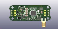
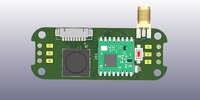
Got a bit of an update. Revision 2 is not that far from the horizon! While the original board is perfectly functional, the geek inside of me was not satisfied and I decided to create an even more capable board :)

It is now using commonly available components that are easy to source (while still being top of the line) but at the same time some things are taken to extremes, to test my engineering abilities and manufacturing capabilities of my partners.

This thing is waaay overengineered with twice as much components as it needs to have, however I just want to be able to gather as much data as I can and analyze it before potentially making it a custom solutions boards for anyone who may be interested in getting one.

So here I present to you my latest revision render board (still need to make some final touch-ups and place texts and references and so on). This board is a bit larger that the viofo one, so I'll be designing a custom 3D enclosure for it, but it all is due to having a LoRa chip on board.

View1.JPG
View2.JPG
 
Yo @bobcat,
If I sent you a Viofo Hardwire Kit, could you somehow modify it so it operates exactly like it does now, but simply add a selection to completely disable the Low Voltage Cut-off?

Would that be expensive, or time consuming?
I’m testing how much power / capacity / run time is left in a dash cam battery pack when the 11.8V selection shuts the camera off.
The dash cam battery pack has an internal BMS that continues to deliver power all the way down to 11.0V or lower.

So far I have determined this last little bit of unutilized power can run an A119 Mini 2 in Low Bitrate Parking Mode for an additional 1 hour 38 minutes.
But I’m having to do that with the plug & play method of parking mode that requires 5 minutes of “inactivity” to go into parking mode, and it’s proving to be difficult.
The difference in power consumption from normal recording mode to low bitrate parking mode is 3.2 Watts vs. 2.1 Watts.
Ideally it only runs in normal recording mode for the first 5 minutes, but sometimes it goes back to normal recording mode.
Having a hardwire kit with the low voltage cut-off disabled would make this testing so much easier.
-Chuck
Hi Chuck,

I believe the voltage cut-off on the original HK kit is set by pulling high/low on IC pins combinations, but since we don't know what IC is used and if it runs any custom firmware it is not possible to make any modifications to it without doing quiet a bit of research and reverse engineering.

However, if you are just running power consumption experiments, you can estimate that additional remaining runtime by doing some math. You'd need to catch that 11.8v threshold and then keep powering the camera in normal mode until the battery runs out, and then recording your additional run time. Since you already know the power consumption of the camera in both normal and park modes, your run time will need to be multiplied by a factor of those.

So the formula would look something like: (remaining hours after 11.8v threshold) x 3.2w/2.1w.

You basically working with Watt/hour calculation in the end, so the dependency on voltage or amp draw is no longer relevant and you should get an accurate estimate for parking mode based on the data you have from normal mode. Btw, your power consumption estimates are in line with mine, I've measured 3w in 1440p/60fps and 2.2w in 5FPS park timelapse on a Mini2.
Thanks for the explanation.
I figured it out;
 
Is this still work in progress? any update?
I've hit yet another roadblock now with shortage of another very tiny component which is impossible to solder in manually. Waiting for stocks to be back up with my manufacturer. Are you asking for the "smart" functionality of this custom design?

Overall I've upgraded to a different dash-cam with USB-C (same principle for park mode sensing communication though) and tested the latest HK4 kit from Viofo and found that they have fixed all the issues and improved the design overall, so unless you are looking for wireless capability or collision detection park mode, the HK4 kit is a pretty good option atm!
Was interested in the HK3 version as my cam has miniUSB.
 
Back
Top