HK3-H hardware kit arrives! (Viofo is not going to be happy about it)

bobcat

Active Member
Joined
Dec 21, 2016
Messages
93
Reaction score
109
Country
United States
HK3-H - the new hardware kit for Viofo dashcams (and most other), where "H" stands for "Homebrew"!

Well, after 3 failed HK3 kits, a year of frustration with random power issues on existing hardware kit leading to missed records, few cases of beers and a free weekend - I have finally designed my own hardware kit that is about to go into assembly and testing! Rest easy Viofo, I am not planning on commercial manufacturing of these and created one purely for my own personal use. After-all this would probably cost at least twice as much if not more as the original kit.

The design relies on quality components where the power circuit is based on military grade integrated converter from TI (why military grade? - because it is the only one I could source that fit my criteria and industrial application rated converters with the same footprint are still in shortage). The logical side is handled by Atmega328P - Yes, I know, a major overkill, but it will allow me to do some other experiments and transmit valuable data for testing.

So, what does it do? Pretty much the same thing as the original kit, but with a lot more finetuning and some expansion capabilities. Below are few stats and ideas:

- fits into existing HK3 casing, but needs manual soldering in place
- supports parking mode
- high efficiency 5V 3A rated Integrated DC-DC converter from TI (can be replaced with up to 10A module in case if I decide to have 20 cameras running at once lol)
- a button for programming low voltage cut-off and other parameters (the integrated DC power module actually supports this by default, but I want to add a delay for cut-off for those moments when battery can dip briefly, such as while starting a car)
- high precision voltage sensor from TI
- led indicator which can be turned on/off
- temperature sensor (mainly for testing)
- data logging stored in long term memory: peak temperature, highest and lowest voltage points, number of car start-ups... whatever else I can come up with
- addition of solder-in module adds ability to transmit data wirelessly to my smart-home ecosystem with remote controls of the HK kit

Wanted to share this with you guys and hoping to hear some feedback and maybe other stupid or crazy ideas for added functionality!

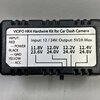
Below are 3D renders of the board. I am planning to order it next week (want to give some time for feedback in case if anyone is interested).

HK_Kit2.jpg

HK_Kit1.jpg
 
How difficult would this be to install? I would definitely be interested in purchasing one depending on the difficulty of installing it.
 
How difficult would this be to install? I would definitely be interested in purchasing one depending on the difficulty of installing it.
It's a drop in replacement for a PCB board on the original kits, so you'd need to desolder 6 wires, remove old board and solder wires back to the new board. It does not have all the wiring, and to be honest I was not planning on the whole wiring thing since replacing existing wiring is a hell of a procedure in my car since it's a convertable and I had to take apart half of the front right side when I've originally installed kits from viofo. So I'm keeping original wiring and just replacing the board.
 
It's a drop in replacement for a PCB board on the original kits, so you'd need to desolder 6 wires, remove old board and solder wires back to the new board. It does not have all the wiring, and to be honest I was not planning on the whole wiring thing since replacing existing wiring is a hell of a procedure in my car since it's a convertable and I had to take apart half of the front right side when I've originally installed kits from viofo. So I'm keeping original wiring and just replacing the board.
Makes sense. So I’m assuming you would be doing all the soldering with the kit in the car? I’ve replaced my kit once and I do not want to do it again lol.
 
Makes sense. So I’m assuming you would be doing all the soldering with the kit in the car? I’ve replaced my kit once and I do not want to do it again lol.
Yep exactly, parking my car next to power outlet, running some extension cords and doing the thing. Done it already a few times thanks to the failed kits.
 
Yep exactly, parking my car next to power outlet, running some extension cords and doing the thing. Done it already a few times thanks to the failed kits.
Awesome! Looking forward to this project and hope you get the first board soon.
 
a button for programming low voltage cut-off and other parameters (the integrated DC power module actually supports this by default, but I want to add a delay for cut-off for those moments when battery can dip briefly, such as while starting a car)
- high precision voltage sensor from TI
- led indicator which can be turned on/off
- temperature sensor (mainly for testing)
- data logging stored in long term memory: peak temperature, highest and lowest voltage points, number of car start-ups... whatever else I can come up with
- addition of solder-in module adds ability to transmit data wirelessly to my smart-home ecosystem with remote controls of the HK kit

It looks like a very interesting project.
I'm guessing you have some experience in electronics and 3D imaging. Nice.

The Viofo version has a delay of 90secs before shutting off when it works correctly.

Some other additions:
A complete power disconnection from the battery when it goes below the Set voltage.
If you don't drive often the hardwire kit will drain the car battery through parasitic loss.
Using the car everyday wouldn't be an issue and no one would notice it.

Data logging sounds really neat at least for nerds, are you able to monitor voltage and current and log them?

In your drawing i didn't see a LH inductor, Is it not required in your design?

How much is the parts list going to cost?
I assume the more boards made the cheaper they will get.

Did you originally build and test a bread board version?

Look forward to more posts
 
That's absolutely brilliant, you've got some serious skills there @bobcat!

Raises a great point that in the grand scheme of things for a camera of todays prices people would be more than happy to pay more for a more capable kit like this.

Is it all the logged data you're outputting over the UART interface? Although see you have the DTR pin so maybe it's for an Arduino / ESP or similar to collect and relay?

It opens up a whole new world of data and would potentially also highlight failing car batteries where voltage on the 12v side drops faster than expected etc, more so in cold weather etc.
 
This is a genius undertaking to improve a good piece of equipment.
I would like to offer an additional improvement.
I would like to suggest additional Low Voltage Cut Off values of 11.6V, 11.4V, or better yet completely disable the LVC off.

During my testing of the BBMC PowerCell 8 dash cam battery pack with the current Viofo hardwire kit, and several different Viofo cameras, A129 Pro, A119 Mini, A229 Duo. The hardwire kit’s LVC off selection of 11.80 Volts would prevent the cameras from operating for an additional 2 Hours 12 Minutes of parking mode recording.

This is because the battery pack would continue to provide power to the dash cam all the way down in the 11.50 - 11.60 Volt range. But when I would use the hardwire kit it would cut power to the camera as soon as it saw 11.80 Volts. So basically the hardwire is preventing the full capacity of the battery pack by as much as 2 Hours 12 Minutes of additional parking mode recording.

-Chuck
 

Attachments

  • 11.80 Volt Cut Off .jpg
    11.80 Volt Cut Off .jpg
    544.2 KB · Views: 24
I would like to suggest additional Low Voltage Cut Off values of 11.6V, 11.4V, or better yet completely disable the LVC off.

During my testing of the BBMC PowerCell 8 dash cam battery pack with the current Viofo hardwire kit, and several different Viofo cameras, A129 Pro, A119 Mini, A229 Duo. The hardwire kit’s LVC off selection of 11.80 Volts would prevent the cameras from operating for an additional 2 Hours 12 Minutes of parking mode recording.

This is because the battery pack would continue to provide power to the dash cam all the way down in the 11.50 - 11.60 Volt range. But when I would use the hardwire kit it would cut power to the camera as soon as it saw 11.80 Volts. So basically the hardwire is preventing the full capacity of the battery pack by as much as 2 Hours 12 Minutes of additional parking mode recording.
So, you're saying that the Viofo HW kits are designed for connection to a car battery rather than a dashcam battery? This makes sense as that is how most people probably use them.

I assume the dashcam battery pack has its own low voltage cutoff to protect itself?
 
So, you're saying that the Viofo HW kits are designed for connection to a car battery rather than a dashcam battery? This makes sense as that is how most people probably use them.
Correct. However, to "fully" utilize parking mode with a dash cam battery pack, and the recommendation of Viofo is to use the 3-Wire hardwire kit.
Without the 3-Wire hardwire kit to command the dash cam to enter parking mode when the ignition ACC is cut off, it takes 5 minutes, of no motion in the camera's view, and no motion detected by the GPS sensor. This means it may take quite some time for the camera to engage parking mode. And during this time it will be using more power, and more SD Card space than if it entered parking as soon as the ignition was turned off.

But yes, this feature I'm suggesting would only be useful to folks who utilize a dash cam battery pack which is a small percentage of applications.
So yeah, I guess I'm being greedy. But to not use the full capacity of the battery pack is like leaving money on the table.
Or having a 20 gallon gas tank, but only being able to use 15 gallons of the 20 gallon capacity.

I assume the dashcam battery pack has its own low voltage cutoff to protect itself?
Yes the battery pack has a built in BMS, (battery management system).
The high is 14.4 Volts, and the low is 11.5 Volts.
 
Thank you for your feedback and input guys! Below I'll try to comment on some of the points:

The Viofo version has a delay of 90secs before shutting off when it works correctly.
Thanks for heads-up! I was planning on setting it to 60 seconds but this will be an easy programming fix if I need to make the delay longer or shorter for any reason. Actually planning on having own logic for that and make the device to repeatedly measure battery voltage multiple times over the delay countdown to make sure it is a true low-voltage situation.


Some other additions:
A complete power disconnection from the battery when it goes below the Set voltage.
If you don't drive often the hardwire kit will drain the car battery through parasitic loss.
It is pretty much a complete disconnect from the battery until next time the car starts! The quiescent current will be in the range of 25uA which is smaller than battery self discharge rate.

Data logging sounds really neat at least for nerds, are you able to monitor voltage and current and log them?
I am able to monitor and log both, however I've opted out from current monitoring for now as I pretty much know what it is.
By the way, I'm pretty big nerd when it comes to data-logging (even recording radiation levels from my balcony lol).

In your drawing i didn't see a LH inductor, Is it not required in your design?
It is integrated inside of the buck module. Part of the requirements that I've set for myself was to find a DC converter with integrated inductor, so that all the inductance and EMI stuff is taken care of by the manufacturer of the IC chip.

How much is the parts list going to cost?
I assume the more boards made the cheaper they will get.
Right now the BOM is around 15$ with the DC chip costing almost 2/3 of the total BOM (since it is a military grade part). It can be swapped for a less expensive industrial/automotive grade parts or parts in different packaging.

Did you originally build and test a bread board version?
I did not, I've run some tests on different components of the design as well as some electrical simulations, but part of the design relies on the very specific resistor/capacitors values which would be hard to adopt to breadboard format (and quiet frankly expensive), so it made sense for me to just straight up design and order the PCB - after all its not that expensive anymore. Most of the parts will be assembled via SMT assembly with the exception of the DC chip.


That's absolutely brilliant, you've got some serious skills there @bobcat!

Raises a great point that in the grand scheme of things for a camera of todays prices people would be more than happy to pay more for a more capable kit like this.

Is it all the logged data you're outputting over the UART interface? Although see you have the DTR pin so maybe it's for an Arduino / ESP or similar to collect and relay?

It opens up a whole new world of data and would potentially also highlight failing car batteries where voltage on the 12v side drops faster than expected etc, more so in cold weather etc.
Thank you sir! You are correct, there is a UART interface as well as ISP (can use both for programming and data logging). The DTR pin is for the onboard programming of the atmega328p via ISP but you are right, I have an ESP32 based hub sitting at home that has LoRa and NRF24 radio modules to receive the signal. Since after initial programming of the module, ISP pins will no longer be needed, I can attach NRF24L01 module to those or if the range won't be good enough, can swap it for a LoRa module and then the whole neighborhood will be able to receive my car's battery status, lol.

To be honest, I'm still undecided whether I want to add wireless capabilities since I already have more than enough of such devices around the house, but I agree with you that with proper implementation it opens up a world of analytics on the car battery.


I would like to offer an additional improvement.
I would like to suggest additional Low Voltage Cut Off values of 11.6V, 11.4V, or better yet completely disable the LVC off.
Thank you for the feedback! The cut-off voltages can be set to anything as it is a programmable value. Realistically I only need one since this will be the testing prototype for myself, but there is a program button already in the design that via some basic LED blinking interface can allow for selecting a value from the pre-programmed range.
 
Correct. However, to "fully" utilize parking mode with a dash cam battery pack, and the recommendation of Viofo is to use the 3-Wire hardwire kit.
Without the 3-Wire hardwire kit to command the dash cam to enter parking mode when the ignition ACC is cut off, it takes 5 minutes, of no motion in the camera's view, and no motion detected by the GPS sensor. This means it may take quite some time for the camera to engage parking mode. And during this time it will be using more power, and more SD Card space than if it entered parking as soon as the ignition was turned off.
I'm actually quiet a bit disappointed with the power consumption of Parking mode on Viofo dashcams, the whole point of such mode, in my opinion, is to significantly reduce resources the camera uses, be it SD storage or power consumption, and the second one has definitely not been taken care of properly. Even the most efficient of the parking modes - the timelapse, barely reduces power usage by the camera comparing to when it is recording in full resolution 4k HDR. There is definitely a room for improvement for these cameras, and I would not be surprised if it could have been improved dramatically with a software fix as most likely some of the power-down/low-power modes are not properly executed in the software.
 
I'm actually quiet a bit disappointed with the power consumption of Parking mode on Viofo dashcams, the whole point of such mode, in my opinion, is to significantly reduce resources the camera uses, be it SD storage or power consumption, and the second one has definitely not been taken care of properly. Even the most efficient of the parking modes - the timelapse, barely reduces power usage by the camera comparing to when it is recording in full resolution 4k HDR. There is definitely a room for improvement for these cameras, and I would not be surprised if it could have been improved dramatically with a software fix as most likely some of the power-down/low-power modes are not properly executed in the software.
As far as parking mode having less power consumption it varies between models.
I've tested A129 Pro, A129 Plus, A119 Mini. A229, A139 Pro, and some camera's power consumption is reduced from 350mA down to 250mA @ 12.60 Volts = 4.4 Watts to 3.1 Watts.
And some camera actually use more power in parking mode. lol
So yes, some software fixes need to be done.
 
I arrived at this thread looking for more information on how the original HK3 triggers the dashcam to going in and out of parking mode in order to make something myself but it seems you are already way ahead :). Where did you find info on how to do this ? Is it sending a message over USB, doing some sequence with the 5V, .... ?
 
I arrived at this thread looking for more information on how the original HK3 triggers the dashcam to going in and out of parking mode in order to make something myself but it seems you are already way ahead :). Where did you find info on how to do this ? Is it sending a message over USB, doing some sequence with the 5V, .... ?
The logic there is pretty simple. The voltage converter board (lets call it that way) accepts constant power 12v from the car as well as Accessory (ACC) power input. Whenever you turn on your car, the MCU on the board reads high signal from ACC-in and then transfers it further a 5v "High" signal to the camera via the yellow cable (which is one of the data pins on the USB input). Whenever you turn off your car, acc goes low and so does the output to the camera on the signal line.
 
Thank you, that sounds simple enough. Do you happen to know which pin exactly is being driven by the signal derived from ACC in (probably a bit hard if you don't have an USB-C breakout board) , because I am not sure if the colors of the cables is universal. I can find a schematic here https://www.pshinecable.com/article/usb-c-cable-wiring-diagram.html which would put yellow at A2/B11 , but I would have expected one of the sideband pins (A8/B8) since they would be perfect for the job.
 
Thank you, that sounds simple enough. Do you happen to know which pin exactly is being driven by the signal derived from ACC in (probably a bit hard if you don't have an USB-C breakout board) , because I am not sure if the colors of the cables is universal. I can find a schematic here https://www.pshinecable.com/article/usb-c-cable-wiring-diagram.html which would put yellow at A2/B11 , but I would have expected one of the sideband pins (A8/B8) since they would be perfect for the job
If you keep their cable, you don't really need to worry about which pin it is as only one USB signal lane is wired. I'm using the Mini B version oh HK3 kit, so would not be able to tell on the USB-C pinout.
 
I was planning to avoid buying the hardwire kit altogether :), but i will keep it as an emergency solution if I can't figure it out otherwise.
 
Back
Top