LTO (Lithium Titanate Oxide) – The Ultimate Battery for Dash-Cam parking mode (DIY)

5S Battery Build Update

I'm making some good progress on my battery build. At this point I'm mostly just waiting on some small parts I ordered to get everything buttoned up.

20250711_202550.webp


I started my build by copying from @GPak's layout, but I eventually opted to mount both the BMS and the charger module directly to the aluminum case.

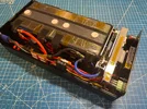
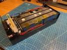
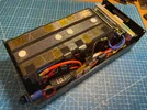
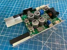
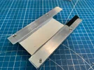
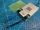
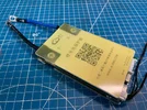
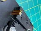
For the BMS, I entirely removed the backplate with the mounting ears, and transferred its hole pattern to the case endplate, along with the sticky thermal pad. To replace the metal standoffs that were embedded in the removed backplate, I cut and sanded some plastic standoffs I had lying around to a length of 5mm. The length of these standoffs is critical to ensure an even and adequate pressure between the mosfets on the back of the BMS, the thermal pad, and the case endplate. The BMS was positioned slightly off-center in the horizontal direction to make room for the wires exiting the BMS, and to also leave an open area on the case endplate for potential future expansions.

20250711_202927.webp


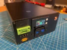
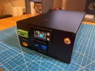
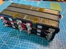
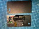
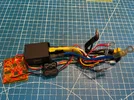
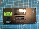
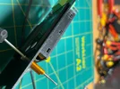
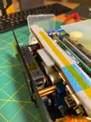
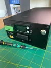
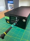
The charger module is mounted upside down on the case's top cover with some thermal paste in between, alongside the UPS module and TDR. I had initially installed the fuses in the recommended inline fuse holders, but found they were taking up too much space and made it hard to run the wires neatly, so I'm now using plain heatshrunk spade terminals as fuse holders. The component and wire layout was carefully decided to ensure the case could be opened like a clamshell (as it is in the photos) without having to disconnect any wires.

20250711_210003.webp


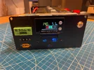
With the charger mounted on the case cover, it appears to be able to sink significantly more heat than when its just isolated in the still air of the case. In the following screenshot, T1 is the temp taken from the top of the inductor on the charger module. This is after ~25mins of charging at 23A in an ambient room temp of around 30 degrees. I could probably push the charge current even higher, but I think the 20-23A range should be satisfactory for my purposes, and I don't wish to put additional wear and tear on the battery for minimal gain.

Screenshot_20250711_030838_BMS.webp
 
Great work @wilsch !

20A charge rate is the practical limit for both the Charger and the BMS, so you have unlocked their full potential.
As for LTO cells, they can be charged at 3C rate or about 60A without any problem. (these are not your ordinary LFP's 🙂)
At 20A charge rate, the cell dis-balance is a bit higher and 0.4A balancing current of the BMS has to work harder to cope with it. (a BMS with 1A balancing current would be better but it is larger in size)

!!! Love the Charger placement and clamp-shell design, I think this is a must for the 20A/240W charging and the best heat dissipation.
I also like the space saving solution on the fuse, I might use it in future builds.

Looking forward to see the final assembly!
 
Last edited:
Awesome implementation @wilsch! Being able to open the case and have everything lay flat on the table is a big deal and will help with any future changes. Sinking the charge board to the case s a great way to go to dissipate heat. I found the charge board is hottest and the BMS is next hottest. My batteries are always the coolest component in the chassis.

275w+ charge rate is pretty quick, though you’ll definitely want a direct to battery connection for any charge rate over about 5-6A. I see your BMS has the sleep function that mine is missing. Perhaps some future version of the software will make it work the way we’d like to see it work.

Congrats on a nice and clean build!
 
Great work @wilsch !

20A charge rate is the practical limit for both the Charger and the BMS, so you have unlocked their full potential.
As for LTO cells, they can be charged at 3C rate or about 60A without any problem. (these are not your ordinary LFP's 🙂)
At 20A charge rate, the cell dis-balance is a bit higher and 0.4A balancing current of the BMS has to work harder to cope with it. (a BMS with 1A balancing current would be better but it is larger in size)

!!! Love the Charger placement and clamp-shell design, I think this is a must for the 20A/240W charging and the best heat dissipation.
I also like the space saving solution on the fuse, I might use it in future builds.

Looking forward to see the final assembly!
I did notice that the BMS struggles to keep the cells balanced when higher current charge and discharge cycles are done in sequence. But in the dashcam application we are cycling between high current charge and a much lower current discharge so at least the balancing can happen in the discharge phase.

Right now I am testing the charging with a 32V/10A adjustable bench power supply. I set the power supply limits to maximum (32V/10A), so the charger board is converting ~32V@/8-10A to ~10-13V@23A. Obviously, this doesn't match the conditions of charging from a car alternator's 13-14V, so the charger efficiency and temp rise I'm seeing right now are not fully representative. I assume that when the charger's Vin is closer to its Vout, the efficiency will be better?

Awesome implementation @wilsch! Being able to open the case and have everything lay flat on the table is a big deal and will help with any future changes. Sinking the charge board to the case s a great way to go to dissipate heat. I found the charge board is hottest and the BMS is next hottest. My batteries are always the coolest component in the chassis.

275w+ charge rate is pretty quick, though you’ll definitely want a direct to battery connection for any charge rate over about 5-6A. I see your BMS has the sleep function that mine is missing. Perhaps some future version of the software will make it work the way we’d like to see it work.

Congrats on a nice and clean build!
Credit where credit is due, I definitely took some inspiration from your build with mounting the charger to the case!

I will for sure be going the direct battery connection route. I'm planning to place the LTO battery in my car's trunk, and luckily the car battery is also in the trunk, so it will be less hassle for me anyways to do a direct battery connection than to run a cable to the interior cigarrete lighter.

I haven't messed around with the BMS sleep setting yet, I'll look into it once I have everything running. Here is my BMS/app info for reference:

Screenshot_20250713_221905_BMS.webp
 
It looks like the hardware and software versions have progressed quite a bit since I purchased my BMS last summer. Mine doesn't have the "smart sleep" function that @GPak does. Perhaps yours will function in a manner that better fits our use case.

I haven't done much measurement of efficiency ratings at different voltage levels, but the published data I've seen all shows 96-98% efficiency. At lower wattage levels, the charger board will be cooler for sure.
 
... Here is my BMS/app info for reference:

View attachment 82674
First of all, I want to apologize, @wilsch , I opened the thread and saw that all your posts disappeared.
I wanted to post and ask why you deleted your posts, but then I saw a pop up message that I am ignoring you???
I don't know how it happened, I must have accidentally hit the button somwhere, :banghead: I didn't even know such an option existed.
All fixed now.
------------------------
My BMS info is attached:
Also yesterday I received a notification on my iPhone about an update to version 5.2.3, although I haven't updated yet.
 

Attachments

  • IMG_8417.webp
    IMG_8417.webp
    45.2 KB · Views: 122
Last edited:
Updated the BMS to the latest version V5.2.3, the update description is "- Optimize display", did not notice any difference.

Also just received a spare JK-BMS from AliExpress.
Same model as my original and the one I bought on Amazon.
It has a Chinese label but no manual, 10G wires soldered and no ears.

The Amazon version came with an English label, detailed printed manual in English, screw terminals with bolts, 10G wires with ring terminals and ears, and is 10mm longer than the Chinese version.

Both versions have exactly the same model number and specs, go figure.
 
Last edited:
I finally finished my 6S LTO battery.
Here are some pictures of the main components and some pictures of the assembly (2 posts due to the 10 picture limit per post).
Next I will post a list of the main features of this battery.
 

Attachments

  • 91.webp
    91.webp
    229.5 KB · Views: 176
  • 90.webp
    90.webp
    231.8 KB · Views: 184
  • 92.webp
    92.webp
    158.9 KB · Views: 165
  • 93.webp
    93.webp
    187.2 KB · Views: 184
  • 94.webp
    94.webp
    242.4 KB · Views: 183
  • 95.webp
    95.webp
    432.2 KB · Views: 202
  • 96.webp
    96.webp
    486.6 KB · Views: 186
  • 97.webp
    97.webp
    509.9 KB · Views: 199
Components:
 

Attachments

  • 101.webp
    101.webp
    550.5 KB · Views: 180
  • 102.webp
    102.webp
    480.3 KB · Views: 177
  • 105.webp
    105.webp
    400 KB · Views: 185
  • 106.webp
    106.webp
    286.2 KB · Views: 176
  • 107.webp
    107.webp
    504.7 KB · Views: 181
  • 109.webp
    109.webp
    499.8 KB · Views: 171
  • 110.webp
    110.webp
    280 KB · Views: 188
  • 103.webp
    103.webp
    462.9 KB · Views: 158
  • 104.webp
    104.webp
    449.4 KB · Views: 180
  • 108.webp
    108.webp
    471.9 KB · Views: 173
Last edited:
That looks like a clean and tidy box, @GPak ! I suppose the lone connector on the back is your jump start harness?
 
I suppose the lone connector on the back is your jump start harness?
Correct, "But wait there's more".... (I remembered a commercial with that phrase 🙂)

Here are the main features of this Battery:

1. 276Wh LTO battery
2. Adjustable charge rate, up to 20A/280W max, including in freezing conditions
3. 3-wire input port for charging from a car battery with ACC trigger
4. Low voltage protection for a car battery
5. Solar charging while parked (common port also used for Auxiliary Battery expansion)
6. Auxiliary Battery expansion, while parked (common port also used for Solar charging)
7. Jump Starter (common port also used for Expandable Battery)
8. Expandable Battery (common port also used for Jump Starter)
9. 3-wire bypass output ports to DVR (powered by a car electrical system while engine is running)
10. USB-C PD3.0 (36W) and USB-A QC3.0 (18W) ports with bypass power (powered by a car electrical system while engine is running)
11. Built in accurate Voltmeter and Battery State of Charge indicator
12. Bluetooth connectivity and App with detailed and accurate battery/cell status and customizable settings
13. Dimensions 80x160x300 mm (3.15x6.3x11.8 in)

Next I will post couple of videos, the first one to discuss this features and functionality, and the second one to show battery internals/assembly and how all this works.
 
Last edited:
Here is the first video.
(Note that all my videos are unedited, so if I misspoke, made an incorrect statement, or missed something, please let me know and I will edit this post with a comment to clarify).

Comment 1:
JK-BMS protections are primarily set at individual cell voltage level.
With the type of connection implemented in this battery, the second BMS cannot be installed in the extended battery.
The JK-BMS of the main battery will protect the extended battery to some extent at the pack level, but will not protect it at the individual cells level.
However the active or passive balancer will be installed in the extended battery to keep the cells balanced.

A Fuse rated for the charging current must be installed in the extended battery or between the two batteries.
And both batteries must be at the same SoC/Voltage level before connecting them.

 
Last edited:
Added important safety related Comment 1, to the post #372 above.
 
Here is a second video demonstrating some of the 6S LTO Battery's functionality.

EDIT:
Comment 1: JK-BMS has one temperature sensor for the MOSFETs, not two.

 
Last edited:
@GPak where did you get the mountable XT60i connectors with pre-soldered wires? I really like the very clean panel you have! Did you use a dremel to cut the metal?
 
@GPak where did you get the mountable XT60i connectors with pre-soldered wires? I really like the very clean panel you have! Did you use a dremel to cut the metal?
I couldn't find the XT60iE pre-wired on AliExpress or Amazon, it doesn't seem to be available at all.
Here is the regular XT60E pre-wired with 12AWG and I like it except it is externally mountable.
XT60E-F connecting cable 12AWG 10/20/30/50CM

I use internally mountable XT60E and XT60iE because it makes it easy to remove the front panel, and in the case of the XT60iE, I think it's the only option available anyway.
XT60E Plug Connector
2PCS/Lot Amass XT60IE-M With Signal 2 + 1 Gold-plated Aviation Plug Connector

As for the cutouts in the metal plates, no, I don't use a dremel (I don't have one, maybe I should buy one).
I drill small holes along the perimeter of the cutout as close to each other as possible (see the attachment), and then use the same drill bit to break the "bridge" between the holes by applying force and tilting it (I've broken quite a few drill bits in the process).
Then I use a file to clean the edges of the cutout to the final shape.
I understand that this is not the best way to cut metal.

Maybe someone else can share their experience cutting metal?
 

Attachments

  • IMG_8498.webp
    IMG_8498.webp
    179.6 KB · Views: 133
Added a handy feature for the battery:
Two brass tubes 2.4 mm ID and 3.2 mm OD, are pressed into the front panel, protruding about 1.5 mm, about the same as the display next to them.
The tubes are wrapped from the inside with several layers of kapton tape to lock them between the front panel and the adjustable resistors for charging current (CC) and low input voltage protection (LIVP).

Now I can adjust the charging current CC and LIVP as I wish without opening the box.
 

Attachments

  • 2 tube.webp
    2 tube.webp
    201.6 KB · Views: 142
  • 3 tube.webp
    3 tube.webp
    157 KB · Views: 144
  • 1 tube.webp
    1 tube.webp
    162.2 KB · Views: 125
  • 4 tube.webp
    4 tube.webp
    191 KB · Views: 125
  • 5 tube.webp
    5 tube.webp
    176.3 KB · Views: 138
  • 6 tube.webp
    6 tube.webp
    158.4 KB · Views: 169
I wanted to copy your design of using the middle third pin for ACC. Unless I add another single pin for ACC. I wish more connectors were available in a mountable fashion - like a small 3 or 4 pin JST to use for dashcam hardwire.
 
Actually, before I found the XT60iE-M mountable connector, I was thinking of using a regular XT60 connector in combination with a small single-pin connector for ACC.

The main requirement for the input connector is the high current rating, preferably 20A and higher. (except for the ACC signal)
The other main requirement is the physical size.
The XT* connectors are the best out there to meet this two requirements.
 
Back
Top