Interestingly, I thought that if this weren't for testing different cameras, but for one specific brand capable of running on a 24-volt system, we could use this 24-volt LTO battery as is.
(would be very interesting to test if it works, but careful, it may charge at very high current. No idea what the original charge rate is, but 1C is 40A)
Or, perhaps, only replace the original board (integrated BMS and charge controller) with a custom JK-BMS and 25A charge controller.
The 25A charge controller is capable of charging up to 60V.
The JK-BMS is available for a 12S+ configuration.
For example:
Viofo's HK4 runs on a 24-volt system.
Car alternator's output is up to 14.8V on a 12-volt system and up to 29.6V on a 24-volt system.
The HK4 should be safe to operate with an input voltage of at least 30V, but I'm not sure about 32V which is required to charge a 12S LTO battery.
I have three hardwire kits from Viofo: HK3-C, HK4, and HK6; and two from Vantrue: VP03(II) and VP05(II). All will run on either a 12v or a 24v system. I wonder what the high voltage limit for each regulator is. On the 12v setting, all seem fairly happy with input voltages up to 19v (limit of my previous bench PSU at the time). I'm reluctant to "experiment" to see how much input voltage they will accept before something blows up. Viofo and Vantrue manuals all specify input voltage of 12-24v.
I'm thinking that reconfiguring the battery to a nominal 12v range provides more usable battery life because each of the hardwire kit regulators have a low-voltage shut off level of about 23.5v. The 12S2P battery will have a fully charged voltage of just north of 32v and a depleted voltage of 20.4v, assuming a low of 1.7v per cell. I'm a little confused, the lower voltage level of LTO cells on the BatteryHookup.com website indicates conflicting information. Some products indicate they can be discharnged down to 0v, others say 1.7v.
@Jeff_Vantrue@VIOFO-Support : What is the maximum safe voltage input level for your voltage regulators before the "magic smoke" escapes from the internal components and things no longer work?
OK, cutting the center busbar and joining cells to form a 6S4P configuration with a voltage range of 11-16v sounds like the clear way to go. I just ordered the larger 25A charger, a BMS, and a doide. I might have enough other parts left over from my previous projects to do most of the work without needing more stuff😎. Looks like the battery pack should arrive within another hour or two, so I'll post pictures tonight.
... I'm a little confused, the lower voltage level of LTO cells on the BatteryHookup.com website indicates conflicting information. Some products indicate they can be discharnged down to 0v, others say 1.7v....
When I first tested the capacity of these LTO batteries without a BMS or any protection, I accidentally dropped the voltage to a 0V on a 7-cell bank, and one of the cells actually reversed its polarity !!!
I didn't think this is possible and thought the cell was ruined.
However, to my surprise, I was able to charge the batteries, including the cell with the reversed polarity, to normal voltage.
These batteries are currently working in my Jeep without any problems.
In practice, I set the low voltage cutoff to about 1.9V for cell, 11.5V for a pack.
Below 1.9V, useful capacity is practically nonexistent, and imbalance builds quickly.
So even if I set it to 1.7V, one of the cells will reach that level much faster, before the others, and the battery pack voltage will still be close around 11.3V which is not far from 11.5V.
If you end up ordering one, they have two different discount codes you can enter at checkout. One is CS5 and the other is DIY (not combinable). Either is good for a 5% discount (~$10).
The battery casing is quite robust and substantial. The batteries are encased in what looks like a custom 3D printed container. You cannot remove or access the individual cells without breaking the case, it surrounds the set of batteries on all sides and has no seams. Here is a side view of the case:
The case itself measures 14 and 1/8" (358mm) long, 7 and 3/8" (187mm) wide, and 4 and 7/8" (122mm) tall. If you include the plastic shields for the "+" and "-" terminals on the end, the length is 15 and 1/8" (383mm). My sample arrived with an overall charge of 27.22v. Each pair of cells measures very tightly, ranging from 2.269v to 2.271v.
Here is the view when you remove the top cover. The cover really just kind of lays there, it doesn't take any real effort to remove it. I presume the PCB is the battery management system.
After removing 21 screws, the circuit board just lifts right off, revealing an electrical insulation pad that mostly covers the busbars.
Removing the black insulation pad (it just lifts off) provides access to the top of the batteries. The busbars are quite substantial and are spot welded directly to the flat battery terminals. This sucker can clearly discharge a serious level of amperage. Do be careful not to drop a metal tool down onto the top of this battery! You’re sure to see an impressive shower of sparks that will set the place on fire!
Each of the busbars has an eyelet attached to it. Here is where connections to an external BMS can be easily achieved with the screws that I removed from the PCB. Attached to the underside of each eyelet is a small nut that appears to be spot welded into place (nice touch). The "arm" for the eyelet is surprisingly pliable given its thickness, you can bend it up with just some gentle pressure from your fingernail. I've circled four of these eyelets in green - these eyelets have a plastic stem sticking up through the hole and thus will not accept a screw unless you break off the plastic stem first. This isn't a problem as the busbars with circled eyelets have another eyelet on the opposite end. This makes establishing new connections to the battery as well as changing the cell configuration relatively simple and secure.
The electrical path of the batteries is shown in the image below, along with the polarity of the battery terminals:
Below s a closer image of the battery on the end that contains the external terminals. I've drawn a green line on the busbar that needs to be cut in order to change the configuration from a 12S2P to a 6S4P battery. I presume a Dremel with a cutting wheel would work sufficiently easily. The only challenge is to attach a new connection to the right-hand side of the freshly cut busbar. I'm not sure what kind of metal this is (again, its relatively soft). Any soldering (if that is possible with this unknown metal) needs to be done with a VERY hot (480c) iron and a very heavy tip to conduct heat as quickly as possible to minimize heat damage to the cell.
I'm thinking that I might remove one of the "redundant" eyelets and experiment with how easily it accepts solder before I attempt to solder one that is attached to a battery terminal. It would be a real shame to damage a cell with heat. If this works, I'll cut the tab circled in yellow and solder it to the adjacent busbar as shown below.
This is the underside of the removable lid for the battery pack. It is relatively thin and flexible. Clearly, this is not a structural element, I'm surmising its primary purpose is to keep the dust off of the PCB.
And here is a closeup of the top of the battery pack casing. As you can see, the outer plastic casing appears to be a single piece with no seams. This is what makes me think it was 3D printed around the batteries. There is no way to remove any of the individual cells without breaking the plastic case open. Therefore, I recommend keeping the cells in their original container - overall, it is quite sturdy.
Here is the set of manufacturer's specs that accompany this battery pack. The official spec sheet is attached.
When I first tested the capacity of these LTO batteries without a BMS or any protection, I accidentally dropped the voltage to a 0V on a 7-cell bank, and one of the cells actually reversed its polarity !!!
Yikes! That would have caused me to panic as well. Glad to hear that the battery cell recovered from a reverse polarity situation! Given the voltage depletion curves for LTO cells, it does seem that once you get to the neighborhood of about 2.0v to 1.7v, any remaining charge just falls off of a cliff, effectively indicating a fully depleted battery.
Wow, very interesting!
The cells are definitely permanently installed and are not intended for disassembly.
The busbars are often made of copper and nickel-plated to prevent oxidation, if so, than soldering the wires should be easy.
The 25A charger doesn't require a reverse current protection diode; at least, I haven't noticed any reverse current.
While you're waiting for all the components, it might be interesting to check the functionality of the original BMS and whether it includes a charge controller.
I'm not sure if you have the time and/or the right power supply for that.
Also, I see a sticker below the main terminals; could you please show the sticker more clearly?
While you're waiting for all the components, it might be interesting to check the functionality of the original BMS and whether it includes a charge controller.
Hmmm... Not sure I'll be able to that. I'll have to search on some of the numbers on the label and see if there is anything I can find. The Toshiba specs (image directly below) indicates that the board functions include "Cell voltage measurement, module temperature measurement, cell balancing, and communication." I don't see any reference to "charging" so I'm presuming a VERY substantial charge controller was connected to the battery's main terminals that are located under the plastic covers on the front of the pack. None of the traces or components on this board appear to be able to handle charging-level currents - all of the PCB components are FAR too small and thin to deal with anything even close to a 10C charge rate. I presume that temperature measurement is instantiated as PCB-level NTC device, there are no additional "probes" or wires that extend from the board into the battery pack.
One interesting result of reconfiguring this battery as a 6S4P is that the specs will match/exceed the specs of my car's main start battery (80Ah, 800CCA). This LTO pack indicates a discharge rate of 350A, but the individual cells are rated at 200A, so I presume it's being down-rated due to the connections and other external wiring. I'm guessing that I'd have no problem pulling 800-1000A (short term) out of this pack as a 6S4P. I'm thinking I'll be able to get somewhere near a few weeks of 24/7 parking mode time out of multiple cameras with this kind of capacity. 😎😀
To make the parallel connections, I'll likely use some 10g (good for 55A chassis wiring) or 12g (good for 41A chassis wiring) wire and crimp ring terminals and just reuse the screw landing pads that the circuit board was connected to. Without the PCB in there, additional jumper wires will fit without any problem. I'll probably just cut off one of the "extra" eyelets and solder it to the busbar that I cut. Nickel plating should solder easy enough, I have plenty of silver solder and liquid flux from my audio projects - just need to be careful to avoid a cold solder joint with all of that metal mass.
The official specs from Toshiba are below. I'm assuming the 45c Ambient Temperature limit is in the context of the PCB and its tiny ICs than for the batteries themselves which seem to have a rating of 55-60c based on specs here and other specs I've found:
Here is an image of the label that is attached to the outer part of the case below the battery terminals. Seems that I'm about to violate the "terms and conditions" of use in multiple ways... Ooops... I hope I won't die as a result😉
Below are some images of the PCB that I removed from the battery pack. The board is quite well made! All of the components are surface mounted and covered with a clear epoxy to provide some electrical insulation and vibration protection.
Toshiba seems to call this board the "Cell Monitoring Unit" which matches the silk screening along the bottom edge of the PCB. The official description of the battery pack is: "The battery module consists of 24 cells (2 in parallel and 12 in series), and incorporates the cell monitoring unit (CMU) that monitors the voltage and temperature of these cells."
Toshiba SCiB™ offers various components such as BMU, main connector, current sensor and electric leakage sensor.
www.global.toshiba
Another page has a slightly different description of a "Battery Management Unit" that is contained inside the battery pack: "Battery packs incorporate a BMU for monitoring cell voltage and temperature; overcharge, over-discharge, and over-temperature protection system; and a charge/discharge control."
Introducing the lineup of the SCiB™ Modules for automotive, public, industrial, power grid, building, facilities and railroad applications.
www.global.toshiba
I haven't yet found a separate high-current device that would provide the function of a "charger." I'm guessing one of those will be EXPENSIVE as these battery packs can be daisy-chained quite extensively: "You can construct a battery system by flexibly combining a single to tens of thousands of SCiB™ modules with other components according to your applications." I'm guessing at the level of "tens of thousands" of these battery packs, the application domain is a battery powered cargo ship or a commercial solar farm. I can't imagine that much battery weight in something that is on wheels. Making a 900v system (electric car) with these battery packs would require approx 33 units, at which point you're look at 1,000+ lbs of batteries.
The CMU/BMU board has a separate daughter board that accepts one 8-pin network cable as input and a second 8-pin network cable. These connections allow for integrating the control of multiple battery units. It's challenging to get a sharp image of the entire board all at once - I'm shooting on an angle in an effort to avoid reflections from my flash.
Bottom side:
Searching Model/Part numbers on the board only leads me to other people selling this same battery pack...
And a QR code that strangely links to a "Taylor Made Sur-Moor T3C Mooring Buoy, 12in Diameter." I can't find anything when searching on T3C1012, either...
Details for the network cable input/output board. It appears to be a simple I/O board - there are no components on it.
And another QR code - I'll have to remake this image, it's a little out of focus:
While you're waiting for all the components, it might be interesting to check the functionality of the original BMS and whether it includes a charge controller.
I'm not sure if you have the time and/or the right power supply for that.
Not sure that I'll be able to do much to make use of the PCB that was part of the battery pack without the original charger unit.
I'm using a Meanwell LRS-200-12 PSU to charge/test my battery pack. It has an adjustable voltage output (11-14v) and can deliver 200w (17A at 12v). I picked it up years ago for a different car-related project and it seems to function well for DIY batteries as well.
According to the description, the CMU monitors the voltage and temperature of individual cells and transmits this data to the BMU.
I'm not sure if it has a balancing function, and it definitely doesn't have a charge controller, so it's useless without the original BMU and charge controller. But....., I think the contacts are gold-plated; some people extract gold from various electronics for living. 😉
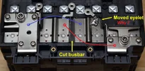
Step one finished: I cut the busbar and moved one of the threaded eyelets to where it needs to be to convert the battery pack from a 2P12S to a 4P6S.
Here is an image of the bottom side of the eyelet. I removed this one from the positive terminal junction and added it elsewhere:
Instead of just "cutting" the busbar, I removed a 1/4" wide strip to prevent it from becoming accidentally connected again. That would be bad. I chewed through two Dremel cut-off wheels to remove the strip. The busbars are indeed nickel plated copper - this became obvious after I clipped off an eyelet with my wire cutters. The good news is that the nickel plating readily accepts solder - I experimented with the strip that I removed from the busbar. A little bit of flux plus a little bit of solder: That was easy... Talk about a false confidence builder!
In contrast, I had a helluva time reattaching the eyelet that I cut from the adjacent terminal. I was using a pretty heavy duty 230w soldering gun that I bough ages ago at RadioShack. I've had good success using this gun to solder lots of heavy things in the past. But the busbars presented an entirely different level of challenge. I was trying to heat the bar while simultaneously preventing over-heating the anode and cooking the battery, so I was using a heavy set of pliers as a heatsink while trying to get enough heat into the busbar to avoid a cold solder joint. It took me several tries to get a joint that I was satisfied with. The first few seemed OK, but I was able to pop the eyelet off with a screwdriver and minimal effort. Darn...
After heating the busbar for what felt like WAAAY too long, I was able to obtain a somewhat messy yet secure solder joint. Copper is very efficient at wicking away heat! I think I'll end up covering the adjacent busbars with electrical tape in the event that vibration from the car allows the eyelet/jumper cable to come loose. I did notice my soldering tip heating unevenly, so I've just ordered a new tip to see if I can do a better job. These batteries have WAAAY too much current delivery capacity to risk having a cold solder joint pop off at some future point.
EDIT: Turns out, my old and trusty Radio Shack heavy duty soldering gun wasn't so trusty this time around. Further poking around revealed the soldering gun was not operating properly. It appears there was a problem with the internal power transformer and it was not capable of delivering full power to the soldering tip. After replacing my old gun with a new Weller heavy duty gun, properly heating both pieces of metal for a good solder joint was quick and easy.
I'm also thinking I'll add a little thread locker to the screws that will hold the eyelets in place. The nut on the eyelets accepts an M3 screw. I'm fresh out of 12g wire, too, so I need to order some more. Bummer...
Public Service Announcement: do be careful to avoid "Copper Clad Aluminum" wire, often abbreviated as CCA. If it looks like a good deal pricewise, it's very likely aluminum wire. For heavy duty applications, you REALLY want actual copper wiring. Search for OFC "Oxygen Free Copper." Speaking of which, Damn! That stuff got expensive over the past few years! I'm not used to paying $1/foot for copper wire... Sigh...
So here is the modified battery after cutting the front busbar and relocating the eyelet, all ready for wire jumpers. That was NOT easy. I'm inclined to agree with the sticker: do not solder... The only other option might be to bend up the busbar, drill a hole, and attempt to get a screw through it. This won't be so easy, that rib in the busbar makes it pretty rigid.
I enjoy reading this thread, even if I only understand about 5% of what is being discussed! I have a Masters degree in engineering, but I only have a basic grasp of electronics.
The power station dashcam battery project stretched my limits, and I wouldn't have even started without the help on this forum.
To provide a screw terminal for the wire jumper. My choices are 1) just solder the wire directly to the busbar - which I now see how challenging soldering is, or 2) move the eyelet and use a crimp ring terminal like I will with all of the other screw terminals already attached to the busbars. I chose the uniformity of using a crimp ring for all of the connections. One thing that I've learned with ALL of my previous projects is that when I work according to the "I'll just have to build it once" philosophy, I ALWAYS end up going back and re-doing some or all of the wiring for one reason or another (usually, expansion related). This activity usually involves lots of cursing and frustration about why I didn't take a more flexible approach the first time. Thus, I am a little reluctant at this point to do any kind of modification that is not "future flexible."
Same here. I probably wouldn't have come up with the idea of building a battery pack on my own, but GPak led the way. I just copied. I've also never been afraid to dig in and cut/solder wires, I've been playing electronics projects since I've been 8 or 10 when my parents got me the 160-in-1 Radio Shack Project kit with the electronics components on the board, a bunch of spring terminals, and jumper wires. Something like this:
I've had a soldering iron in my hand since I was 10 and the scope/complexity of my projects has only grown over the years. From time to time, I wonder what I might have majored in had I not chosen computer science (I have three degree in this field). I'm thinking it would have been electrical engineering...
To provide a screw terminal for the wire jumper. My choices are 1) just solder the wire directly to the busbar - which I now see how challenging soldering is, or 2) move the eyelet and use a crimp ring terminal like I will with all of the other screw terminals already attached to the busbars. I chose the uniformity of using a crimp ring for all of the connections. One thing that I've learned with ALL of my previous projects is that when I work according to the "I'll just have to build it once" philosophy, I ALWAYS end up going back and re-doing some or all of the wiring for one reason or another (usually, expansion related). This activity usually involves lots of cursing and frustration about why I didn't take a more flexible approach the first time. Thus, I am a little reluctant at this point to do any kind of modification that is not "future flexible."
I enjoy reading this thread, even if I only understand about 5% of what is being discussed! I have a Masters degree in engineering, but I only have a basic grasp of electronics.
It's actually not that complicated.
I'm an Aerospace engineer with no prior experience in electrical or electronic engineering.
However, curiosity is a powerful motivator, and I like to set and solve interesting problems.
Since the design is modular, there is no need to design PCBs, write firmware, or anything else that requires specialized in-depth knowledge.
The real challenge was finding high-quality components that were properly matched to work together, and of course, assembling it all into a compact enclosure.
The real challenge was finding high-quality components that were properly matched to work together, and of course, assembling it all into a compact enclosure.
When working with my students, I generally refer to this type of situation as "the iPhone moment." I argue the iPhone was NOT a revolutionary or "break-through" product, rather it is merely the assembly of already existing (and mostly boring) other technologies into single package. We already had cell phones, screens, wifi, processors, memory, cameras, GPS, rechargeable batteries, etc, etc. It is their integration into a single and easily portable device that is novel. Each constituent part had already existed for quite a long time before the iPhone had its "moment." Interesting product that has new utility? Sure. A radical breakthrough? Hardly...
Here is a bit of an update as I continue to wait for additional parts to arrive in the mail. The larger 25A charging board arrived today - it's quite a bit larger and beefier than the 20A one that is in my 6S battery pack! The good news is that AliExpress has stopped using DHL as their importer/shipper, so I didn't get nailed with an additional huge tariff. The last thing that I purchased on AliExpress was a ~$20 item. I had a tariff charge of about $4 as expected, then DHL added a ~$20 fee to collect and process the tariff! Needless to say, I was happy to see them partnering with a new delivery company.
As I highlighted above, four of the eyelets on the battery have a plastic column protruding up through the threaded hole. Using a pair of needle nose pliers, I was able to wiggle and break it off so the eyelet is now usable. Then, I just lifted the eyelet a little and removed any remaining bits of plastic underneath. Now all of the eyelets are usable 👍
I also discovered that my old soldering gun was having some electrical "issues" - it seems the power transformer wasn’t delivering sufficient power after 40 years of use. This is what led to my difficulty with moving the eyelet and soldering it to an existing busbar. So, I picked up a 200/260w Weller D550 gun. This made quick work of reflowing the solder joint for the new eyelet! I partially cut the ridge in the busbar to prevent the heat from wicking away in different directions and used a heavy set of metal pliers as a heatsink to protect the battery terminal from becoming overheated. This worked great and I was able to achieve a MUCH better solder joint with much less time and effort. While it doesn't win any awards for neat soldering (there is way too much solder there and I was trying to work quickly to prevent overheating the battery terminal) this is a secure solder joint that I'm much happier with. It's clearly not a cold joint.
Then I covered the busbars with some Kapton tape as a first step in preventing trouble in the future. Here is the battery with all of the new jumpers in place. I used 12g wire for the jumpers, and after way too long, I finally picked up a good quality ratcheting crimping tool - highly recommended! This successfully converts the battery from a 2P12S configuration to a 4P6S configuration. Battery voltage is now 13.6v with 80Ah and 1104Wh of capacity (equal in capacity to my car’s main start battery!):
I marked the heavy external terminal polarity with a sharpie and I'll use these points for connecting the BMS and Charger boards. I'll use the remaining eyelets for connecting the BMS balance wires. As I complete the final wiring, I'll apply some blue or red Thread Locker on the screws to help keep the jumper wires in place and I'll tape over the remaining eyelets as a extra safety measure. The good news is that the original plastic cover that came with the battery still fits on top exactly as intended.
After a little slip with my wiring, though, I have new appreciation for the comment about not modifying the battery because of risk of death. The available amperage makes this battery a VERY effective arc welder for ring terminals. 😮😮
Excellent work, Eric, it looks neat and professional.
A faulty soldering gun just proves that the right tools make a big difference: they make the job easier and improve its quality. I've encountered this many time.
I was wondering if it you could use the original cover and you confirmed it. 👍
DHL's $20 handling fee for a $4 tariff is insane.
I've never had to pay any duties separately, only what's included in the original order.
I noticed that since the introduction of tariffs, AliExpress has started adding an additional charge to orders (I assume it's related to tariffs).
And the goods are delivered directly to my home without any intervention on my part.
Thankfully, in my region, I've never seen DHL deliver goods from AliExpress, Temu, or Amazon.