A119 files still corrupting after capacitors changed

Vincy Gav

New Member
Joined
Jun 27, 2020
Messages
18
Reaction score
2
Location
London
Country
United Kingdom
Hi guys,
I bought an Viofo A119 (version 1) in 2016 it was a very good dash cam but now think it has done its day. Did updated the software on it twice, the later one had included a park mode that was never there when new so was handy instead of using motion detection as a surveillance when parked up.

Last year it seemed to be playing up. I have had it hard wired to the car since new. Firstly every-time I switched the engine on, it would corrupt the last recorded file before the engine was switched on then also the dashcam would cut off. I would have to press the power button to turn it back on. That was not too bad and liveable. I even thought it was the SD card and changed for 2 different ones and same thing.
This year it has been getting worse that some of the files in park mode which end with P and some of the normal filming drive modes do not work and get corrupted. This is in mp4 video mode as it has always been. The message 'Windows Media Player cannot play the file. The Player might not support the file type or might not support the codec that was used to compress the file.' happens on certain files when opening from the computer.

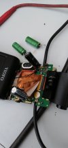
I noticed the top of one of the capacitors was slightly bulged and thought it came to the time to replace them. I did this 2 days ago and realise that it hasn't seemed to make a difference. They are brand new capacitors of the exact same value, so a bit confused as to why this is still happening.

Anyone know any other tips or I think it would be just going in the bin. It is pointless in having it if it is now corrupting video files when driving as that is when it is needed most.
 
Can you measure the voltage across each of the capacitors (2 measurements)?
(While powered.)
 
I would give it a try this evening or tomorrow.
 
Post the results when you do, they should both have the same voltage of about 2.4 volts once charged, and should both drop by about the same small amount when the power is removed.
 
I have tested it under various conditions. It is no way near 2.4volts
I am getting between 0.017-0.02volts after a long drive both capacitors. With the camera off and unplugged it gave 0.02volts (2mV)
There doesn't appear to be much difference with the camera on standby, monitor switched on, or unplugged and turned off. Highest value I got leaving it overnight unplugged which was 2.3mV

I also realised that it doesn't even seem to know the difference between park and drive now.
Camera was off, switched it on, went for a drive yesterday around 12:30pm, files seem to be recording. Parking up switched off car at 13:38 Car is recording normal mode still, then from 14:16 onward files are corrupted and it failed to enter park mode recording. Then at 17:30 files are back to normal and not corrupted, still not in parking mode. Corrupts from 18:06, back on at 18:24, corrupt 18:44, back on 19:22, corrupt 20:32, on 20:38, corrupt 20:44. Com back to car to go home, start car at 21:37 camera is still on when I switch engine on and has not powered off completely, however it then records 2 files as park mode at 21:37 and 21:39 then from then on goes back to normal mode recording, however all files corrupted up until 22:27 when I switch off car. It then goes into Park mode recording from 22:29 but all files still corrupted.
 
Seems likely that you don't have the capacitors connected, check the voltage on the PCB pads if possible. How did you connect them? Photo?

It is also possible that whatever supplies power to the capacitors has failed, but I haven't heard of that happening before.

(I recommend cutting the leads of the old capacitors and soldering the new ones to the remains of the old leads, not extracting the leads out of the PCB which is more risky.)
 
It's possible that the cap charging circuitry has failed, but I've only heard of this type of failure with LiPo cams, not supercap ones. Still a possibility though.

It is clear that for some reason the caps are not charging properly so you've found the problem, now all you need is to determine what needs to be fixed which I hope is quick and easy. If you changed to cap leads at the PCB, take a good look to ensure that it's not a double-sided board connection; if so you may need a dab of solder on the opposite side. Easy to miss this kind of thing ;)

Phil
 
I guess I should have cut the old capacitor. I completely took the old one out then soldered new one in. I did put solder on both sides. I would check over connection; although strange none are getting enough power. I wish I had check older ones before I removed them.
IMG-20200701-WA0015.jpeg
 
I wouldn't be surprised if one of your solder connections is not making contact with the PCB, maybe try checking continuity using the multimeter between the capacitor leg and PCB track, maybe at another component if you can follow the track there.

When soldering you need enough heat on both sides of the join, while also having a little flux available, needs a thin tip on the soldering iron but a reasonably powerful soldering iron for large components like that, also need to limit the amount of time to avoid damage.

Although you did it the right way, far easier to avoid board damage or poor joints if you solder to the old legs - that comment was more for people doing it in future than saying you did it wrong.
 
Those solder joints look problematic (looks like they just balled up). Maybe try placing the solder gun tip on the opposite side of the board and try to get the solder to suck through.
 
Add flux before doing a re-heat, that will increase the chance of a good bond. Flux pens are cheap, easy to use, and work wonderfully just the way I like things to be ;)


Remember that solder flows towards the heat so touch the soldering iron where you want the solder to go and it will find it's way there, ie both the PCB pad and the cap leg together at the same time. On double-sided boards I like to do the component side first but I'm not sure that it matters as long as both sides connect well.

Phil
 
Were the old caps soldered on the top side of the board, looks really strange as it’d expect the legs to go through and then soldered in the under side?
 
The old caps were soldered at the bottom, the new ones I had soldered at both top and bottom. I also noticed they are shaky. I am going to remove them now and start from scratch.
 
If your soldering skills may not be 'up to snuff', any good computer repair shop can do the job for you and with the cam apart, the cost will be very reasonable. If their tech is on premises they might even do it while you wait ;) An offer of a pint might be enough now that your pubs have reopened :cool:

Phil
 
I have got a multimeter and did various tests to the board. The input is getting over 5 volts from the USB connection. Around the board a lot of the rectangular gold contacts when viewed from the bottom are negative. A lot of the circle gold contacts are positive. These range from over 5 volts, 4 volts and 1.5 volts.
When I removed the capacitors from the board testing the points gave very little voltage, so I think I probably damaged the board. Only one of them had a good earth testing it and one of the gold positive circles gave full voltage. The part where the positive legs would go in gave 0.02 volts.
Thanks for the help guys but think this camera may end up in the bin. I have done soldering on a lot of jobs over the years, this one seriously defeated me.
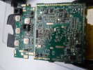
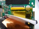
DSCF1967.JPG
^Underneath board with new capacitors in^
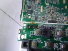
DSCF1968.JPG
^underneath board^
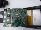
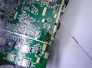
DSCF1969.JPG
^board from above^
DSCF1970.JPG
^Board from above, capacitors removed^
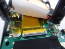
DSCF1972.JPG
^board from below capacitors removed^
DSCF1973.JPG
^board from below capacitors removed^
 
Looks like the traces were lifted or destroyed through excess heat. You ain't alone if you did that- I've done it too, and not so long ago either. There's a good chance this can be saved so take heart before you bin it. If there's enough left to know where the traces connected to, a skilled tech can jumper the missing parts with either wire or solder, restoring the circuit path well enough to make it work ;) I'd be sure to have them glue or otherwise secure the caps down when done so that they don't pull the repair loose driving over bumps. Probably cost you more than a pint, but still far less than a new cam.

I wish I'd made pics, but I once had an old Pioneer home stereo amp, and one of the output transistors died. I asked a friend to source the part for me but he made me an offer to replace all 4 and their drivers for $20, less than 2 output transistors would have cost me new from the local electronics store. I handed it to him and about a week later he shows up at my door. He comes in, sets it down on the table upside down, and pulls the cover saying "Look". My jaw hit the floor; unknown to me some previous owner had apparently dropped the thing. The entire PCB had been broken completely in two, and dozens of tiny traces had been painstakingly bridged with solder and the board rejoined by a clear glue of some kind. You could see some age discoloration in the glue- this was old work and not my friends doing. His work looked magnificent. It had never shown any problem at all till the output blew...

Phil
 
I gave the board a clean up and removed everything completely and started from scratch. I used new flux, also created new pads by using conductive paint. One of the capacitor appears to be powering up well and going up to around 4.5 volts, then around 3 volts iirc. The other capacitor tried re soldering checking voltage etc but no cigar.
The best I have got it to is around 0.7 volts. The negative terminal seems good, it appears the problem is the positive terminal. Would it make sense to bridge the positive terminal from the other capacitor, or is this too risky.
 
They are 2.7 volt capacitors aren't they?
That means they should never be charged above 2.7 volts.
Hopefully you are measuring it's + relative to 0V on the PCB, not measuring between its legs?
Would it make sense to bridge the positive terminal from the other capacitor, or is this too risky.
I think that would be a bridge to the negative terminal of the other since they should be connected in series. (not 100% sure on that).
 
The unit will charge each individually (to valance them out) but the output is combined (in series), to give 5 about 5 to 5.4v. If one cell is not charging or is bad, then the battery bank will not give an adequate output.
 
Back
Top