SG9665GC anyone hardwire?

yes we're working on a couple of things, once we have that ready Jon will be in touch to arrange to replace some things for you, still a couple of weeks away at least at this stage

just on that you prefer a hardwire solution or cig plug?

Actually I would prefer the hardwire solution. But I'd like something where I can plug both GC's through one converter. I realize this would probably require one 15' cable to allow for routing to the rear mounted GC.

Thanks

Fred
 
Actually I would prefer the hardwire solution. But I'd like something where I can plug both GC's through one converter. I realize this would probably require one 15' cable to allow for routing to the rear mounted GC.

Thanks

Fred
separate convertors is probably more practical, you could wire them to one location but individual supplies leaves a bit more headroom in the power supply, would much rather give you two and do it right, we're just working on that now, will make sure you're updated once that's tested and done
 
Thanks for the fast replies earlier. I have a CPUSB01 converter on the way and now I'm choosing crimp connectors for it; can you tell me what gauge (AWG) the input wires are?
 
Thanks for the fast replies earlier. I have a CPUSB01 converter on the way and now I'm choosing crimp connectors for it; can you tell me what gauge (AWG) the input wires are?

I'll wait for Jokiin to confirm, I used my digital calipers.
Insulation = 1.13 mm (across/wide, not Diameter)
Bare Wire = 0.6 mm (across/wide, not Diameter)
Based on what I googled up that's 16 AWG
 
Would recommend soldering rather than using crimp connectors
definitely, in my career I have seen soo many dodgey crimp connections after a while of being in use with building up resistance that the device on the end starts to play up, or in case of modern cars if someone crimps aftermarket a connection to the cars computer it starts throwing fault codes with built up resistance. I always solder, never have this issue.
 
Sometimes my Air Force electronics experience pays off. I learned how to solder properly in a 12 month Electronic Warfare tech school. (but it's not that complicated) :)
 
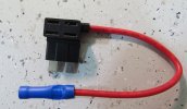
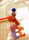
Well, I just wanted to ask the group a few questions about hardwiring. So I've attached a few photos of the hardwire kit and fuse adapter that I've got.

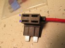
The fuse adapter looks like it has 2 fuse slots on it. Are we actually supposed to put 2 fuses in it? Which fuse is for what? And what amperage do we use? Is it okay to use a slot on the fusebox that always supplies power so as to keep the dash cam recording 24/7?

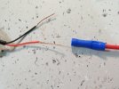
How should the bare wire leads from the hardwire kit/power supply be connected? I'm assuming the red wire goes into the fuse adapter inside the plastic blue thingy? And how do you actually connect the bare stranded wire? Do we just crimp the blue shell with plyers with the red wire fed into it, or are we supposed to somehow solder it? I don't see how you could possibly solder it when the blue shell is in the way.

And, where does the bare black wire lead hookup to? Thanks.
 

Attachments

  • IMG_0373.JPG
    IMG_0373.JPG
    394.6 KB · Views: 34
  • IMG_0374.JPG
    IMG_0374.JPG
    411.8 KB · Views: 33
  • IMG_0375.JPG
    IMG_0375.JPG
    182.1 KB · Views: 33
  • IMG_0376.JPG
    IMG_0376.JPG
    154.1 KB · Views: 44
Well, I just wanted to ask the group a few questions about hardwiring. So I've attached a few photos of the hardwire kit and fuse adapter that I've got.

The fuse adapter looks like it has 2 fuse slots on it. Are we actually supposed to put 2 fuses in it? Which fuse is for what? And what amperage do we use? Is it okay to use a slot on the fusebox that always supplies power so as to keep the dash cam recording 24/7?

How should the bare wire leads from the hardwire kit/power supply be connected? I'm assuming the red wire goes into the fuse adapter inside the plastic blue thingy? And how do you actually connect the bare stranded wire? Do we just crimp the blue shell with plyers with the red wire fed into it, or are we supposed to somehow solder it? I don't see how you could possibly solder it when the blue shell is in the way.

And, where does the bare black wire lead hookup to? Thanks.

5Amp is best in the #1 slot closest to the new wire. (IMG_0376.JPG) You should use what ever the original fuse was for the #2 slot. The new fuse is there to protect the car not the dashcam. So yes you need two fuses, the original, and the new 5Amp one. Yes you can use an always energized such as power seats etc. (don't use air bag!) This will let the camera record 24/7 and you can use the optional motion detection, or let it record full time if you want.

Red goes to the new add-a-circuit crimp. (you need a wire crimp tool, flat plyers might smash it wrong)
Solder is always prefered if at all possible for long term reliability. You wouldn't use the blue crimp, you'd cut/strip and use another method.

Black goes to the bare metal frame of the vehicle (ground)
 
Last edited by a moderator:
Well, I don't have any crimping tools, but I do have wire cutters and a nice soldering iron with some Kester 44. So I guess it would be best to clip off the blue tube with wire cutters, strip back some of the insulation on the fuse adapter, and solder the two red wires together? Then I guess I'll wrap it in electrical tape?

Or is there a better method? Thanks.

Slipping on a heat shrink tube first is usually the best choice. I don't like how electrical tape falls apart in the heat and gets all gummy after awhile. (sticky mess)

https://www.google.com/webhp?sourceid=chrome-instant&ion=1&espv=2&ie=UTF-8#q=how to solder wires together
 
atm-fuse-holder-jpg.129
 
Last edited by a moderator:
im totally anti-crimp connection person, I solder only.

I've seen many installs over the years where people have crimped insulators rather than wire and wondered why they had issues, solder and heat shrink is always my preferred option
 
I've seen many installs over the years where people have crimped insulators rather than wire and wondered why they had issues, solder and heat shrink is always my preferred option
and ensure that there are no pointy sharp bits of solder sticking up before heat shrinking, I have seen people do this and it has broken through the heatshrink and shorted out on the car frame once.
 
Great information from all and that photo is awesome. Thanks. So I guess it works out to where one fuse could trip, but not the other? We basically have 2 fuses in parallel, but with different amperages. It's a little confusing, because when things are in parallel, I thought it was with both polarities, like when you have batteries in parallel.
 
Back
Top