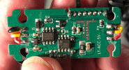
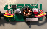
HK3 hard wire kit - terrible voltage regulation

I can see a possible variance from batch to batch, both of HWK's and cams both, where individual pairing could lead to problems or not. In that kind of 'marginal' situation, a switch to lamp cord for lower resistance could make just enough difference to cause the stated results for that one situation.

We like to see performance and specs as solid numbers, but in everything electronic there is some variability, which is why component tolerance is mentioned in schematics where a out-of-tolerance component might cause erroneous results. I think we all can agree that in these two units which have been put to the 'scope, the resulting ripple found is very excessive. So now I think it needs to be found whether this problem is widespread and if so, then how many are like this.

These are all built cheap so we will not possibly get the best from them, but they should be reasonably good by design and there should be enough QC to ensure that defective units do not become common in the hands of buyers.

More testing is needed throughout a wide range of production times to know for sure what is going on here. Only then can we properly analyze the test results to give a complete and accurate view.

Phil
 
...but still it was "designed" for a battery (so no wonder that "ripple filtering is poor")
Not trying to be smart here, genuine question.
You do realise that the HK3 is the source of the ripple right?
So regardless of power supply it will be there.
The amount will vary based on input voltage and load.
I tested this before and basically the whole system works at <=3.3V so as (could be) expected A129Pro works even at 3.3V via USB
Ok, i've not tested this but common electrical engineering sense says this is impossible.
There is a thing called 'dropout' with regard to regulators. Basically the voltage has to be a particular amount above the output or the regulator 'drops out'.
For a real example, the Texas Instruments 1117A 3.3v regulator has a dropout voltage of 1.3V max with a 1A load.
This means that for the 3.3v regulation to be maintained the incoming voltage needs to be 3.3v plus the dropout voltage (1.3V) for proper operation.
That means the input voltage needs to be maintained above 3.3+1.3=4.6 volts.
-source https://www.ti.com/lit/gpn/REG1117
The camera probably doesn't use the 1117 (well it might, i don't have one here at the moment) but it will use something with similar qualities.
Theory dictates that unless the input of the camera has a buck/boost regulator it will not operate with a 3.3v input, and stands a good chance of being unreliable under about 4.6v depending on the reg it does employ.
(<3.5V LCD flickers, <3.3V starts to shuting down in 2CH/<3.1V starts to shuting down in 1CH) that was the reason i wasn't buying that whole "lamp cable" solution of yours (more like another HWK Vpp overshoot issue or a cable issue, and the capacity or a better connection of the lamp cable saved the day)
The issue i suspect is actually under voltage, but you have some interesting findings there.
You'll have to pardon me for being skeptical until they are backed by another source.

Also in fairness, people should be sceptical of my findings also until they have been verified.
It's how science works.

I can see a possible variance from batch to batch, both of HWK's and cams both, where individual pairing could lead to problems or not. In that kind of 'marginal' situation, a switch to lamp cord for lower resistance could make just enough difference to cause the stated results for that one situation.
We like to see performance and specs as solid numbers, but in everything electronic there is some variability, which is why component tolerance is mentioned in schematics where a out-of-tolerance component might cause erroneous results. I think we all can agree that in these two units which have been put to the 'scope, the resulting ripple found is very excessive. So now I think it needs to be found whether this problem is widespread and if so, then how many are like this.
These are all built cheap so we will not possibly get the best from them, but they should be reasonably good by design and there should be enough QC to ensure that defective units do not become common in the hands of buyers.
More testing is needed throughout a wide range of production times to know for sure what is going on here. Only then can we properly analyze the test results to give a complete and accurate view.
Phil

This person knows it.
You've described the situation completely as I understand it.
I don't think these 'faulty' units are 'faulty' at all. I think they are all bad, and the combination of a low tolerance input on the camera, combined with a slightly poorer than average couple of regs has lead to this.
This is exactly why i want to test more units. I suspect they all have rotten regulation, as even a cursory glance at the crude circuit reveals.
I suspect that as new models of cameras came along with higher power requirements this was bound to hit a tripping point.
I suspect the 'failure' rate on these is very low....... until you power a 1amp camera with them, and even though they still might mostly work, i think the percentage of HK3's not working when used in conjunction with an A129 will be more significant.
This is the underlying reason i test at both 500mA and 1A, as the result is different with different loads.

Keen to do more testing, don't have the cash to 'self fund' this research, but happy to test on anything anyone will send me.
If it means enough to some people i'd consider accepting cash donations, but i'd have to become comfortable with the idea.
I am not a formally trained electronics engineer, so i'd want people to consider that first.

Just being objective based on the glance of the circuit in the HK3 i think it is wide spread, and possibly not limited the the HK3.
If i were a product manager or engineer or something i'd be testing my brands units in house.
A possible compromise could be to only supply this regulator for use with low power cameras and commission a new design for higher power cameras.
That should nip the initial issue in the bud, and once these are all phased out move across to the better regulator for all devices.
I'm sure many of these units are having issues that are being experience by people not using forums like this, and thos issues are possibly not making it up the chain to the manufacturers.

Not sure what a lamp cord is..., can anyone fill me in? Hope i'm not missing something obvious.. Just a different kind of USB cable?
On the subject of cords, the gauge of wire, both negative and positive will play a large part.
My first test was at the output of the regulator, on the regulator PCB, and showed a low of 4.52v .
Testing again with the cord in the equation showed the dashcam would have actually seen a low of 4.12, 400mV less that the voltage measured at the PCB.
If I cut this cord to be 6 inches (150mm) long I suspect it may power the A129 with no apparent issues.
 
Last edited:
If my ohms law is right this time of the morning i calculate the loss to be an additional 240mV, and given how rough the incoming regulation is you'd need a giant filter / reservoir cap in the dash cam to compensate, which it simply don't have, not for an incoming voltage with such a gross swing.
So cable resistance = ~ 0.24 ohms (Rohde&Schwarz HMC8012 multimeter leads nulled out)
Current - 1A (Dash cam running with GPS and rear camera attached)
Voltage = 4.52 (average reading at low point)
We're looking at an additional loss of 240mV, so 4.52v - 0.24v = 4.28v
I need to post a correction to this.
My Ohms law was right....., but something was missed.
In a DC system the negative / ground cable also has to be factored in.
I will assume the same size conductor is used for the negative in the USB cable.
Thus the losses are doubled, so 4.52v at the PCB minus 2*240mV = 4.04v
The math now results in a figure not grossly far from the 4.12v actually measured at the end of the USB cable under load.

This was an afterthought to the above post.

Interesting to consider the issue is compounded.
A higher power draw camera brings the reg into worse performance and lower low voltages, and then compounds the issue as the higher current also causes further losses over the cable.

I've been thinking about how i would engineer the system, and the honest reality is that I can't come up with a way that doesn't still have a 'gotcha'.
For example... why not just take the vehicle system voltage straight to the camera and regulate there?
Then your low voltage cut-out would be based on a voltage measurement that is effected by the resistance of the cable to the camera and the losses incurred.
There are 'ways' around all this... but covering all bases would make for an expensive unit and difficult install.

At this point my side project is to re-work the existing design with tighter regulation and possibly a minor increase in voltage to accommodate the resistive losses without breaking usb spec if I can.. say 5.1 to 5.2v with a goal of <100mVpp ripple.
Say worst case 5.05v under a 1A load with a 500mV loss over the length of cable we'd still have a minimum of 4.55v hitting the camera with a heavy load.
 
Not trying to be smart here, genuine question.
You do realise that the HK3 is the source of the ripple right?
So regardless of power supply it will be there.
The amount will vary based on input voltage and load.
This is not about whether there will be the ripple or not, it's about 1.6-2.6Vpp on your side and 480-640mVpp on my side difference. Are you aware that oscillators (or potential oscillators) are possible to be affected even from outside? (which can change their working range or cause wider deflection)

Btw: I didn't see anywhere you've checked what is it inside so FYI it's build around HX1336. Guess which of the measured outputs is closer to the specs...

Ok, i've not tested this but common electrical engineering sense says this is impossible.
There is a thing called 'dropout' with regard to regulators. Basically the voltage has to be a particular amount above the output or the regulator 'drops out'.
For a real example, the Texas Instruments 1117A 3.3v regulator has a dropout voltage of 1.3V max with a 1A load.
This means that for the 3.3v regulation to be maintained the incoming voltage needs to be 3.3v plus the dropout voltage (1.3V) for proper operation.
That means the input voltage needs to be maintained above 3.3+1.3=4.6 volts.
-source https://www.ti.com/lit/gpn/REG1117
The camera probably doesn't use the 1117 (well it might, i don't have one here at the moment) but it will use something with similar qualities.
Theory dictates that unless the input of the camera has a buck/boost regulator it will not operate with a 3.3v input, and stands a good chance of being unreliable under about 4.6v depending on the reg it does employ.
Simple, world is not just about popular 1117, there are also switching converters with much lower dropout voltages or LDOs (even tens of mV) and some of them are even able to pass the input when it's below certain amount (so hypotetically, after it crosses, lets say, 3.5V, it's connected directly to input <3.5V, which is conveniently about what it needs anyway). But yeah, not sure about reliability on 3.3V, i tested only about 10minutes and i was a bit worried about the LCD.

I checked my images from A129Pro and unfortunately don't have anything which captures much of the internals behind USB, so have no idea what's inside.

The issue i suspect is actually under voltage, but you have some interesting findings there.
You'll have to pardon me for being skeptical until they are backed by another source.
Well, i wasn't interested in to get on the bone of what actually gets to the chipset, so could be the case. I only tested lower voltage at the USB input. But I bet the internal regulators have fixed outputs...

...
For example... why not just take the vehicle system voltage straight to the camera and regulate there?
...
Yeah, i never gonna get why so much manufacturers still uses 5V. Especially when things get power hungry and a current rises, wires starts to be a problem, especially at longer distances.

I bet even A139 still uses 5V... (I'll check it as soon as I have time)
 
Last edited:
The A139 uses the HK3C (USB-C plug) but I don't have a HK3 to compare mine to so there could be more difference than just the plug. Both are 5VDC output.

There are (or were) cams which used a 12V power scheme, but putting the power regulation in the cam adds heat there which is not a good idea, nor is having the switching mode EMI so close to the processor.

My main complaint has always been the use of USB mini connectors; I've had plenty of trouble with that. The use of 5VDC doesn't seem to be a problem. A side-effect of using USB connectors is that people can and do swap things around thinking they're all the same because it all plugs in together, and we know the problems that causes.

"Lamp cord" is a flat molded 2-conducter cable, usually 16 to 18ga, consisting of stranded wire in a flexible sheath. Has a high strand count so the 'skin effect' allows better conductivity for DC along with improved flexability. For this discussion just consider it as 18ga wiring; plenty good for the purpose.

What all this really boils down to it that these devices are made to the cheapest price point possible, and the cabling is made as small as can be cheaply done too. In essence they barely work, but that's usually enough for the intended purpose. Betterment is certainly possible, and without much additional cost. Spending even just $1 more in manufacture would greatly improve things and also reduce the potential for all manner of issues such as operating glitches, early cam death, and EMI.

Given that PS issues are one of the top 2 cam problems it's clear that better needs to be done.

Phil
 
Fun fact, HWK for A139 has slightly different design. :geek:

5.4V at the end of the cable, constant 50-60mVpp with(even without) load across 0.5-1.5A via HD35. With A139 hooked up, after few seconds it jumps from 50-60mVpp to 250-290mVpp (non-standardized wave, probably rather something leaks back).

HK3C
20210320_114710.jpg20210320_115443.jpg

HK3
20210320_124350.jpg20210320_124505.jpg


I bet even A139 still uses 5V... (I'll check it as soon as I have time)
The A139 uses the HK3C (USB-C plug) but I don't have a HK3 to compare mine to so there could be more difference than just the plug. Both are 5VDC output.
Yes, i was lazy enough to not even check the sticker, when i've wrote that. :giggle:
 
Last edited:
This is not about whether there will be the ripple or not, it's about 1.6-2.6Vpp on your side and 480-640mVpp on my side difference. Are you aware that oscillators (or potential oscillators) are possible to be affected even from outside? (which can change their working range or cause wider deflection)
Totally aware. Hence why testing was done with a resistive load connected at 2 different common current draws for typical cameras, thus favouring the HK3 to do it's best work.
I think it's been made clear that they're not all the same, even the 2 i have tested have different output figures, they just happen to be worse than working units.
Lab power supplies are by design intended to be as pure as reasonably possible. They are the standard as far as testing like this goes and are engineered to have as little effect as possible on the DUT. I could use a battery, but the result will be the same.
There are so many tangents that could be run off on for testing, have to draw the line somewhere.
Btw: I didn't see anywhere you've checked what is it inside so FYI it's build around HX1336. Guess which of the measured outputs is closer to the specs...
Didn't get that far, but based on what you've found that is a pretty disappointing device vs the price of this unit to the end user.
Just opinion, that's all.
Just noted, the switching frequency is specified to be 100-150KHz (130HKz Nominal) I thought I was getting much less than this, 1,538Hz <<-- this is interesting, incredibly slow, seems it might explain the massive flopping around of the output.
You able to measure yours? Wouldn't surprise me if it were much tighter.
Simple, world is not just about popular 1117...
I thought I made that clear. It was chosen as a random example.
In a situation like this passing the input when the input is low and/or poor is a bad idea that will quickly lead to unpredictable behaviour of the camera.
Not saying they don't do that, just saying it's a bad idea. I don't have a camera here to open.
...there are also switching converters with much lower dropout voltages or LDOs (even tens of mV)
I wasn't aware such regulators existed, just out of curiosity could you link 1 or 2? Could be handy to know for future.
Yeah, i never gonna get why so much manufacturers still uses 5V. Especially when things get power hungry and a current rises, wires starts to be a problem, especially at longer distances.
Agreed, they need a 3 pin connector if they want acc to trigger park, or possibly something clever like placing a trigger signal on the positive line small enough to not effect the units operation.
I noted in recent browsing BlackVue has 12v operation straight to the camera with LVC configurable in the cameras menu.
Only issue there is the current draw over the line to the camera will throw out the voltage reading for LVC, but then if the cable is kept at a constant length this could be compensated for.


There are (or were) cams which used a 12V power scheme, but putting the power regulation in the cam adds heat there which is not a good idea, nor is having the switching mode EMI so close to the processor.
Blackvue does it. With a well designed high efficiency regulator and other appropriate consideration neither hear nor EMI will be an issue
As a crude analogue to the idea, imagine how much noise is in a laptop PC all around the CPU, memory and various bus and data lines.
My main complaint has always been the use of USB mini connectors
Whilst not optimal i have no issue with it, providing what comes out of the connector is compliant to USB specs.
I can see though that if someone were to plug in a USB supply capable of only 500mA into a device sucking 1A the mixup could cause issue, are these the troubles you're suggesting?
"Lamp cord" is a flat molded 2-conducter cable
Oh... actual lamp cord.. well..... that would solve a lot of issues regarding voltage drop over cable lengths.
I won't knock it, it's a great idea if you can accommodate it in your cable runs.
Problem is that we need a 3rd conductor for the ID / parking mode pin, but this can be done!
What all this really boils down to it that these devices are made to the cheapest price point possible, and the cabling is made as small as can be cheaply done too. In essence they barely work, but that's usually enough for the intended purpose. Betterment is certainly possible, and without much additional cost. Spending even just $1 more in manufacture would greatly improve things and also reduce the potential for all manner of issues such as operating glitches, early cam death, and EMI.
It's an achievement to be nastier than my nasty no name ebay regulators!
That said they do use a (or a counterfeit of a) MP1548, a pretty reasonable regulator.
And... BASTARDS!!!! they are a whole DOLLAR each now!
https://www.ebay.com.au/itm/122278776730Yes whilst these things have been designed to be adequate, they are certainly no where near optimal.
Given that PS issues are one of the top 2 cam problems it's clear that better needs to be done.

Phil
Well... i don't normally hang out on dashcam forums, you can all see I'm a new account.
And i'm here for..... power supply issues.
Can i take a guess that memory cards are the other issue? Do i get a prize if I'm right.


Fun fact, HWK for A139 has slightly different design. :geek:

5.4V at the end of the cable, constant 50-60mVpp with(even without) load across 0.5-1.5A via HD35. With A139 hooked up, after few seconds it jumps from 50-60mVpp to 250-290mVpp (non-standardized wave, probably rather something leaks back).
Yes, i was lazy enough to not even check the sticker, when i've wrote that. :giggle:
Great pics and info, so seems they did indeed change the regulator.
In a hurry to go now... but did i see a mention of output cable compensation in the datasheet for one of those regs?
Looks like an ideal feature that could compensate for a known length of cable.
 
@v81 You win the prize! :cool: SD cards are indeed the other usual problem.

My complaint about USB is mechanical, not so much electrical. After numerous plug/ unplug cycles things loosen up leading to faulty connections. USB was designed more for stationary semi-permanent use where it does well, but is not so good for this use. Somehow it's become 'standard' for dashcams and I feel like slapping the person or persons who started us down that road, when far more suitable connectors existed then and now :mad: And the electrical standard is 500mA which might have been enough for the first cams but isn't now. People will try to use whatever plugs in so if a cam needs 1500mA it shouldn't be compatible with a 500mA plug system.

Better builds and computers/ phones have better designs for shielding against EMI but heat remains an issue for our use. Not easy to resolve when the chipsets are not designed to use 12VDC nominal inputs, again harking back to the days of only desktop computers with multi-voltage PS's. That won't change for us when dashcams are a minuscule market segment of chip sales. But that doesn't prevent use of better designs and better components with better shielding in our dashcams and their PS's :cautious:

When you step back and look at dashcams (and action cams too) what you see is a thrown-together collection of parts which do work when put together, but are rarely specifically designed for the exact purpose we put them to. There has been and is a reluctance to break out of the mold restraining us from getting a better product. Few cams do not use MicroSD, Mini-USB, cabling meant for other purposes to remote cams, poor mounting schemes, SDK choices instead of bespoke programming and more. No cam has more than one or two things from outside of this "box" so we keep seeing the same problems over and over and they're never truly solved :cry: Cheap and nasty is what is being sold, so cheap and nasty is what we buy...

Phil
The USB specifications are freely available from www.usb.org. It goes into far more detail than you want to know about.
A USB master is only required to supply 100mA of power. A device is required to request permission to draw more, and then is allowed to draw up to 500mA.
USB chargers follow a different specification. They use pull up and pull down resistors on the data lines to tell devices how much current they are capable of supplying, up to 2A.
If manufacturers actually implemented these specifications, there would not be a problem. Most laptop computers just connect their 5V supply to the power pins of the USB ports with no current limiting. Because of this device manufacturers have been ignoring the specification and drawing as much power as they want without negotiating, or checking.
USB cable manufacturers seldom tell you what gauge of wire they use. So getting a particular set of devices to work together is trial and error for the user.

USB A & B connectors were robust, but nobody liked them because they were huge.
USB mini A and mini B were reasonably robust, and much smaller, but nobody ever built equipment with the USB mini A, so it has been discontinued.
USB micro A and micro B connectors are slightly smaller than mini A and mini B connectors, but they are horribly fragile. This is the only type of USB connector I have ever broken, and I have broken several of them. Thankfully new devices don't seem to use them.
USB type-C is about the same size as mini-B connectors, they have the same connector on each end, and they are not keyed, so they plug in easily. You never have to reverse them. USB type-C is actually about as robust as the mini-B connectors, so they learned from the disaster of micro connectors. Unfortunately, USB type-C cables contain electronics, they do not all have the same capabilities, and you can't tell by looking at the cable what it is capable of. USB type C comes with a new power specification that allows higher currents, and higher voltages, but the devices must communicate with each other, and the cable to negotiate for these higher voltages and currents. So far, there aren't many devices that take advantage of this. Probably because you can't easily tell the cables capabilities, and the cable must support these higher currents and voltages.
 
...A USB master is only required to supply 100mA of power. A device is required to request permission to draw more, and then is allowed to draw up to 500mA...
...Most laptop computers just connect their 5V supply to the power pins of the USB ports with no current limiting...
...USB cable manufacturers seldom tell you what gauge of wire they use. So getting a particular set of devices to work together is trial and error for the user...
You know the hell that I live in!
Standards are great, it gives engineers solutions to previously solved problems so they can ignore those solutions and go and create new problems!
Also the other great thing about standards, there are so many different ones.
And if you get bored you can go create a new one!

...USB type-C cables contain electronics, they do not all have the same capabilities, and you can't tell by looking at the cable what it is capable of. USB type C comes with a new power specification that allows higher currents, and higher voltages, but the devices must communicate with each other, and the cable to negotiate for these higher voltages and currents. So far, there aren't many devices that take advantage of this. Probably because you can't easily tell the cables capabilities, and the cable must support these higher currents and voltages.
Pretty sure there are USB C to C cables that have no electronics, and that just makes matters worse.
Not being able to tell them apart... this is probably the worst thing USBIF has done.
Or is it the changing of the naming of USB 3.1 / 3.2 the worst thing they did?
I'm at the point where I'm ready to toss the idea of USB and welcome an entirely new peripheral connector.
USBIF has lost the plot.

With a straight face and completely seriously, and my dad is probably lurking here.
How the hell does the ordinary non technical person operate in this bull**** modern world?
Dad is only just starting to use USB C for charging mobile phones, but down the line as the bleeding edge USB C devices become basic and ubiquitous in an ordinary household how the hell is my mum and dad going to cope when even i, a technically minded person struggles.
Thanks the bull**** USBIF pull, and similar actions in all kinds of tech the ordinary person is going to be facing some pretty massive challenges in the comming 10 or 20 years.
 
As a side note, one should never refer to the USB version number when attempting to refer to the USB speed. A device can rightly claim that it is USB 3.2 compliant, but only work at USB low speed (the speed designed for mice and keyboards).
The speeds are:
Low speed: 1.5 Mbps
Full speed: 12 Mbps
High Speed: 480 Mbps
Super Speed: 5Gbps
Super Speed +: 10 Gbps, 20 Gbps, and 40 Gbps (seems they screwed up here and did not give the highest three speeds different names).

Edit: While verifying the actual speeds, I noticed that ALL connectors other than USB type-C have been depreciated. This is good news.
 
Are we talking USB 3.2 Gen 1x1 or USB 3.2 Gen 2x1 or or USB 3.2 gen 1x2 or USB 3.2 gen 2x2.
Gotta love it. there are at least 4 different flavours of USB 3.2 alone.
When will the madness end.

Good News.jpg
Viofo on these forums, who where the last I contacted for support are the first to reply.
Not sure where a replacement will be shipped from, but something is happening I hope.

Just thinking about the really low switching frequency i'm seeing.
I wonder how many of them meet their spec for switching.
There's a change they ripple could be bought down to be very low at the right frequency, but of my tests and the others mentioned they all seem to have a slow/low freq.
Bad batch of reg chips?
Or reg chip making promises it can't keep?

Have found a reg that can do up to 3A, up to 30VDC in and has the ability to be configured to compensate for a known wire resistance and claims <20mVpp ripple.
Problem is... i cant find a source in Australia.
Would love to knock together a prototype.
 
Totally aware. Hence why testing was done with a resistive load connected at 2 different common current draws for typical cameras, thus favouring the HK3 to do it's best work.
I think it's been made clear that they're not all the same, even the 2 i have tested have different output figures, they just happen to be worse than working units.
Lab power supplies are by design intended to be as pure as reasonably possible. They are the standard as far as testing like this goes and are engineered to have as little effect as possible on the DUT. I could use a battery, but the result will be the same.
There are so many tangents that could be run off on for testing, have to draw the line somewhere.
Ok look, i only asked whether you've tried a battery. You haven't. Thank you for the answer.

I'll pass the whole mumbling about "as pure as possible" because you clearly haven't struggled with things which are very sensitive to input, noise etc. Sure, it was probably too much to expect from HK3 to be that sensitive but sometimes something can "hit the spot".

Didn't get that far, but based on what you've found that is a pretty disappointing device vs the price of this unit to the end user.
Just opinion, that's all.
Just noted, the switching frequency is specified to be 100-150KHz (130HKz Nominal) I thought I was getting much less than this, 1,538Hz <<-- this is interesting, incredibly slow, seems it might explain the massive flopping around of the output.
You able to measure yours? Wouldn't surprise me if it were much tighter.
Hold a sec, do you literally mean 1,538Hz (1538/1000Hz, not 1538/1Hz)? (sorry, sometimes i get confused by comma and dot used in numbers across languages) If so, then no wonder it's that bad.

Anyway, on my side, it is and it isn't. :D The unit i was talking about the whole time is quite unstable (about 400Hz-110kHz, based on more than one factors) and that's why i adviced to you in one of my first posts to check it as well.
But I cut open a second HK3 unit now and it's 136kHz with load (without load 110kHz) almost rock solid :D, about 460mVpp (so probably this is how it should work).

I thought I made that clear. It was chosen as a random example.
In a situation like this passing the input when the input is low and/or poor is a bad idea that will quickly lead to unpredictable behaviour of the camera.
Not saying they don't do that, just saying it's a bad idea. I don't have a camera here to open.

I wasn't aware such regulators existed, just out of curiosity could you link 1 or 2? Could be handy to know for future.
Well, just a cheap and common linear regulator isn't the best example.

E.g. you can check some here: https://www.ti.com/power-management/linear-regulators-ldo/products.html

Great pics and info, so seems they did indeed change the regulator.
In a hurry to go now... but did i see a mention of output cable compensation in the datasheet for one of those regs?
Looks like an ideal feature that could compensate for a known length of cable.
Both, HX1336 as well as NDP1335, should have cable compensation, if i recall correctly.


Now i wonder whether old HK3 will ever get the updated circuit... :unsure:
 
Last edited:
ok received my A129 VI ....do you want me to post it to you to test or I guess I can do it with my rigol and PSU...but need to know your protocol.

Probably better to send it...???? Ill await your reply

I've use PTN7806W little swmode PSUs...3A capable wide range Voltage input....extremely high efficiency there are other with fixed 5V OPs ...similar. Yes these are more expensive than flebay units but very efficient and reliable
 
Last edited:
ok received my A129 VI
No worries..
My standard is as follows..
Clean linear supply or battery as the source.
Test current draw with no load
-- Note current drawn

If you have a DC load connect load at 500mA and then 1A and measure voltage & current at HK3 input and again at mini USB connector if possible.
These figures can then be used to calculate input / output power, and thus efficiency.
-- Note input & output power & efficiency
Repeat for 500mA and 1A load.

With scope probe set to 1x and BW limit enabled (20MHz) coupling DC mode you'll want to be aroun 1 or 2v per division.
Turn on Vmin and Vmax measurement as well as statistics, have the menu up ready to reset statistics.
With tongue at the right angle test the voltage at the end of the USB cable (i used the exposed terminals on my DC load for this).
Once probing is reliable hit the reset statistics option and then wait 10 or 20 seconds for Vmin average and Vmax average to stabilise.
--Record these 2 figures.
Repeat for 500mA and 1A load.

Now switching to AC coupling and ~ 50, 20 or 10 mV per division as required, trigger at a reasonable point enable Vpp measurement in measurement menu.
Probe again, and when tongue angle is just right reset stats and monitor for Vpp avg to become stable
--Record this figure.
Repeat for 500mA and 1A load.

Should end up with power in and out, efficiency, average minimum voltage, average max voltage and ripple.

I had done a lot of my testing at 10x and that will have lost me some resolution.
I'll do a final round of testing when i have some more units on the bench, and re-test the ones i have at the same time.

You're welcome to send if if you'd prefer, i'd be happy to have a play with it.
If you want to go this way PM me for details.
 
OK I ran my A129 4K @12V DC (Using one of my Linear PSUs) thru HK3, ran fine for 15mins plus.

I draw was initially ~450/550mA then dropped to 200/220mA.

As said I don't have an active load, I understand their use but never needed one yet....that said I could use one...maybe.

So I'll send you my HK3

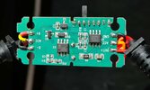
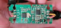
Looking at the PICs (Pg2) the NDP1335KC is a DC buck converter 3.1A OP capable (soft start 93% efficient, cable drop compensation, ) its a simple device but does the job....I cannot make out the other SOIC IC.

EDIT: CHIPSEA 32P20 appears 12 BIT OTP MCU .......

Brendan
 
Last edited:
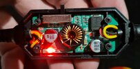
@wasyoingonce2 Yeah, HK3 has the CPU's printing etched off completely and the regulator's is about to fade, but as i mentioned before it's HX1336 (knowing this i think the print should be more recognizable now)
 
So I'll send you my HK3
32P20 appears 12 BIT OTP MCU .......
Using an MCU for cutout, not a bad idea.
I have 2 or 3 units coming that I'll be paying the postage on to return.
I'll leave it at that for now, I suspect in a weeks time I'll have some results up.
I suspect these might work ok if they can switch properly, at least per the data sheet.
Will be interesting to see if the efficiency improves too.
 
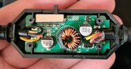
Ok I opened my HK3 took some pics its quite different internally to the other images.

As shown its different simpler but similar to the HK3C uses: CHIPSEA 32P20 and NPD1335KC buck converter

I odered an electronic load DL24P 180W.....I need to have the cable included in the "load" for accurate measurement. In the mean time I'll so the measurements using resistive loads

IMG_3329 small.JPG

IMG_3326 small.JPG
 
Last edited:
@wasyoingonce2 Nice, because two versions would be too easy... In the meantime viofo follows this thread, hiding in a corner, with a popcorn and evil smile on his face. :ROFLMAO:

Anyway, it looks like something between HK3 for A129Pro and HK3-C, so an evolution actually happened, that's nice. Now, how are we able to tell the difference without tearing it apart? :unsure: (or without special equipment, i assume it has similar output to HK3-C)
 
Last edited:
Back
Top