HK3 hard wire kit - terrible voltage regulation

In the mean time I'll so the measurements using resistive loads
I may be stating the obvious, but your resistive loads are capable of handling 12 W right? Burned resistors smell terrible, and the smell lingers for days.
 
hahaha yeah I have quite a few 1ohm 10W ceramic resistors ...I won't stress the PSU too much I have an active load on the way.
 
ok 1st results I haven't done full tests and IMHO I don't have an issue with my HK3 PSU. Infact its very good.

Test doine with 12V DC in, limited to 1A. CC.

Tested PSU with 10 0hms resistors cobbled together (actually I started with 10 ohms 5W (actually measured @9.9'ish ohms I cal checked my meters prior to use) and Its was producing 5.04A. The resistor placed at the output of the unit not thru the USB and leads....which can probably effect the test a lot. It go quite hot so I changed the load resistor to a 10ohms load with various 10Wresistors cobled together (actiall 9.9-9.3 ohms) and I was drawing was 550mA.. Still significant!

Anyway to cut to the chase my HK3 PSU only put out spurious low noise no funny sawtooth ramping voltage. 1st run ....just microvolts hash .JPG
Original run using 5V 10 ohm. Just noise on OP, AC coupled.

another DC oupled run again now saw tooth output minor hash.JPG
Another run DC coupled...note no sawtooth

DC coupled just smal hash no sawtooth issues (1).JPG
Another DC couple run note the voltage...its not right as this is measured at the unit not thru all the USB cable....thats why I need a linear active load to test it properly

2nd  run ....just microvolts hash again .JPG
Typical hash on OP DC coupled.


Linear PSU .JPG
My Linear PSU output


current small.JPG
measuring current....


setup small.JPG
Dodgy setup testing.....

Ok the results show I have no problem with my HK3 PSU. I will test further when I get the active load as using resistors is a pain and burning experience fraught with, one mistake its all over. I'm off to hospital for a short procedure so cannot test in next few days but I will be back at it

Cheers the results...My HK3 is perfect. oh I isolated my power PSU with an isolation transformer. I could isolate the oscilloscope instead. Sorry for the camera screen shots...its just easier but very unprofessional. I just do screen grabs

So atm my HK3 is perfect and a damn good unit well worthy.

Brendan
 

Attachments

  • 1st run ....just microvolts hash .JPG
    1st run ....just microvolts hash .JPG
    106.9 KB · Views: 18
Last edited:
ok one thing...in the images above the "Typical hash on OP DC coupled."

DC coupled just smal hash no sawtooth issues.JPG
This is not right here...its showing a greater Vpp and I have the horizontal range too low. Something not right here.

I need to re-do this but as said will be away for next 2 days

cheers

Brendan
 
Got a delivery yesterday.
2 x HK3's from, an unknown source in Amazon packaging.
I suspect this is thanks to Viofo on this forum.
Disappointing that Viofo Australia has still not returned contact to me, even if they are aware of this thread it would be nice to see "Hey, we see you had some issues and see our head office has responded. If you need anything else reach out."
But just silence. :(
Will test these units in the next few days.
 
About the Vpp reading...
I am very rusty on 'scope use and never knew it deeply at any time, but wouldn't you see this value shown in all 4 places if there were one single 600mV transient and the rest was steady?

Trying to learn here ;)

Phil
 
About the Vpp reading...
I am very rusty on 'scope use and never knew it deeply at any time, but wouldn't you see this value shown in all 4 places if there were one single 600mV transient and the rest was steady?

Trying to learn here ;)

Phil
Not sure what you mean by "all 4 places"?

If you mean the images above, you need to look at the scale in the bottom left corner, 10V | 5V | 10mV.
 
Yeah that reading is not right I don’t know why I’ll do it again. It shouldn’t be the same

But the ripple I found and saw was very little. But my HK3 is different circuitry

cheers
 
Not sure what you mean by "all 4 places"?

If you mean the images above, you need to look at the scale in the bottom left corner, 10V | 5V | 10mV.
Circled in red on post#64. If the voltage peak-to-peak max is 600, the min is 600, and the current reading is 600 then it would average 600. And according to the left scale it's max at 600. So if the set-up is right, and my thinking is correct, it could be a very stable 600mV fluctuation.

Guess we will see on the re-test. Nice to see the initial problem shown isn't with them all (y) Now to figure out whether others are bad and if so which ones. And if it's batch-specific it would be nice to know what the bad component is.

Everything learned and shared here benefits everybody so many thanks to those doing the testing :cool:

Phil
 
The ripple should be measured in with AC coupling, and i think with a time base long enough to capture the ripple.
I think the measurement is lost in the noise with 5v per division on the vertical scale and thus the ripple measurement is low res and consistent, but only due to the lack of resolutions with the scope settings, not because it's clean.
well don't be too harsh they did send some....looking forward to the test results
Will be testing in the next 24 hrs. Not being harsh on Viofo Intl, just Viofo Australia, who i still have not heard from after submitting a ticket and following up with a phone call.
Viofo Intl responded within hours and I have the units they sent.

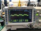
Here is a sneak peak at one of them...
DS1Z_QuickPrint24.png
17.3mV of ripple... clean as a whistle.
For anyone not used to a scope it might look bad, but we usually 'zoom' in a bit to see the waveform clearly.
The vertical scale is in the bottom left, 5mV per division, so quite a fine measurement.

Exact same chip and circuit as the faulty units, but different colour (shade really) solder mask, could mean anything really, but possibly different manufacturer, or simply incontinences in solder mask being used.

Voltage is high, >5.5v not sure why they do that as the reg in use has the ability to compensate for the lead length to be sure 5v is reaching the camera.
To be clear this >5.5 is measured with a 1A load at the end of the lead too.
Far cry from the 4.15V in the faulty units.
The DC:DC conversion is pretty efficient, but with that high voltage if the regulation in the camera itself is linear this is going to be overall less efficient and will increase heat.
Half a watt in addition to heat previously generated at 5.0v in a confined space is enough to spare a thought about.
Given we've had 2 faulty in a row i wonder how many there were.
I'd be happy to test the units for the seller, but not sure they would be interested.

Overall i'm being a little nit picky on the replacement, it seems as if it will be sufficient to do the job, and it's stats are much improved.

Thanks to Viofo for sending them, and doing so very quickly.
 
Last edited:
Many thanks


yes I did AC coupled (above) but had hard time triggering as the signal was low and jittering. My Ripple values match that you just mentioned 17mV. I' waiting for my electronic load but the resistive did work. But measuring at the converter voltage at the unit is a problem as it doesn't allow for copper cord losses....that another reason I need the "load".

Good to hear the others are better.

Maybe the original had component issues or a bad batch?

Cheers

Brendan
 
Voltage is high, >5.5v not sure why they do that as the reg in use has the ability to compensate for the lead length to be sure 5v is reaching the camera.
I suspect it is mainly so that there is still a reasonable voltage by the time it reaches the rear camera, the regulator is not compensating for the front to rear lead.

The DC:DC conversion is pretty efficient, but with that high voltage if the regulation in the camera itself is linear this is going to be overall less efficient and will increase heat.
I would be very surprised if there was a linear regulator in the camera, it certainly sounds like it uses switching regulators.

Good to see it working well, would be interesting to see it with the real load, see what is causing radio interference for some people. Your last image doesn't look like it should cause much in the way of rfi.
 
Exact same chip and circuit as the faulty units, but different colour (shade really) solder mask, could mean anything really, but possibly different manufacturer, or simply incontinences in solder mask being used.
And those faulty ones you have use HX1336, right? If so then that explains why it's used even with USB stepdown convertors where are more tighter specs, without complains on internet. :unsure:
 
I suspect it is mainly so that there is still a reasonable voltage by the time it reaches the rear camera, the regulator is not compensating for the front to rear lead.
I doubt the rear camera would be an issue, the current it draws is trivial, as will be the associated voltage drop.
The total power drawn by the system hardly changes weather or not the rear camera is connected.
In my admittedly limited testing in situ the current draws changes more dependant on resolution and encoding quality selected.
I would be very surprised if there was a linear regulator in the camera, it certainly sounds like it uses switching regulators.
The navman i have on the bench here has a linear regulator as has a Garmin unit i looked at a while back.
It's really quite common to find them in devices where the voltage drop across the reg is small (ie 5v to 3.3v in the case of the Navman).
My Blackvue however has a switcher internally, but it's natively 12-24v in.
But that said, can't rule it out.
Thinking it over a bit more though, if they did have a switcher, why not run 12 or 24v straight to the unit and do away with the HK3s internal reg?? would solve a few problems and wouldn't stop them from still offering a hard wire kit (as BlackVue do).
Good to see it working well, would be interesting to see it with the real load, see what is causing radio interference for some people. Your last image doesn't look like it should cause much in the way of rfi.
Will be fine with the real load. Dad is super keen to finally get this put to bed.
I will do some limited RF testing, but i only have fairly crude instruments for RF.
I might pop my IC-7300 on the bench and see if that gets upset by it.

And those faulty ones you have use HX1336, right? If so then that explains why it's used even with USB stepdown convertors where are more tighter specs, without complains on internet. :unsure:
Those any many other regs would be used in all sorts of things with and without complaint.
Not sure what you're getting at?
 
I suspect it is mainly so that there is still a reasonable voltage by the time it reaches the rear camera, the regulator is not compensating for the front to rear lead.
I doubt the rear camera would be an issue, the current it draws is trivial, as will be the associated voltage drop.
Well, while i was testing the lowest possible voltage, the rear camera was hooked up by the 5m USB cable so the voltage drop indeed isn't that much of an issue.

Thinking it over a bit more though, if they did have a switcher, why not run 12 or 24v straight to the unit and do away with the HK3s internal reg?? would solve a few problems and wouldn't stop them from still offering a hard wire kit (as BlackVue do).
Good point. The only thing i can think of is the possibility to use USB connector. That rises a question at least for A139 which could use the potention of USB-C specs...

Those any many other regs would be used in all sorts of things with and without complaint.
Not sure what you're getting at?
Nothing. I just wasn't sure when you've said "exact same chip" whether it's the HX1336 or NDP1335 or something else. (since there is the updated version of HK3) In case of HX1336 would be mean that even the "second rock solid" unit of mine is basically faulty :D .
 
Last edited:
I doubt the rear camera would be an issue, the current it draws is trivial, as will be the associated voltage drop.
Interior LED IR lamps take a bit of power, the A129 Plus now does the video encoding for the rear in the rear camera, and we now have 3 channel cameras, the HK3 needs to support all these.
The navman i have on the bench here has a linear regulator as has a Garmin unit i looked at a while back.
It's really quite common to find them in devices where the voltage drop across the reg is small (ie 5v to 3.3v in the case of the Navman).
Maybe it is a good way of stopping the microphone picking up switching noise, but that is still a significant amount of unnecessary heat generation, especially when using lithium batteries! I would be surprised if Viofo used a linear regulator for anything that uses significant power.

Thinking it over a bit more though, if they did have a switcher, why not run 12 or 24v straight to the unit and do away with the HK3s internal reg??
Not sure, but using USB means that it can be plugged into a computer for file access and a USB powerbank for parking. Overall I think people feel more comfortable/safer with a USB powered camera.

Even on USB-C, they are still using the 5.? volts when they could have stepped it up to 9 volts within the USB-C spec., but the A139 seems to do much better on power regulation anyway, especially for the remote cameras.
 
@Nigel Just two corrections. If "3CH" refers to A139, then that uses a bit different way of power delivery. And USB-C offers up to 20V. :giggle:

EDIT: Forgot to mention, at least for A129Pro, there is something inside which slightly reduces voltage for the rear camera (means input's power isn't directly connected to the USB for the rear camera).
 
Last edited:
@Nigel Just two corrections. If "3CH" refers to A139, then that uses a bit different way of power delivery. And USB-C offers up to 20V. :giggle:
The USB-C on the A139 uses the default 5 volts, it does not request higher voltages even if they are available. Electrically it is the same as the A129, just uses a different connector. (A much nicer connector that clicks into place and can be inserted either way around.)

Internally it is somewhat different, especially the power supply to the remote cameras which goes over thin coax cable.
 
The USB-C on the A139 uses the default 5 volts, it does not request higher voltages even if they are available. Electrically it is the same as the A129, just uses a different connector. (A much nicer connector that clicks into place and can be inserted either way around.)
I'm perfectly aware of that...

You've been talking about the (probable) need for slightly higher voltage than 5V in combination with rear cameras, IR, 3CH, etc. I've only pointed out it doesn't matter for A139 because it uses different way of power delivery for the additional cameras than just "connect this wire with this one".

And the fact that USB-C specs offers up to 20V, not just 9V.

Internally it is somewhat different, especially the power supply to the remote cameras which goes over coax cable.
That was my point. I assume they uses something like a MAX9271/MAX9272 combo as e.g. Blackvue does. I was begging for this change so when A139 came out, it was almost no brainer for me.
 
Back
Top