HK3 hard wire kit - terrible voltage regulation

Interior LED IR lamps take a bit of power, the A129 Plus now does the video encoding for the rear in the rear camera, and we now have 3 channel cameras, the HK3 needs to support all these.
I don't know what's in it, all i know is that the power used by the system barely changes with and without the rear camera.
I was under the impression the A129 Plus had no IR LED's... I certainly can't see where they would be.
From what i can determine, a healthy HK3 should be able to do double the power the A129 Pro Duo requires quite comfortably.

Maybe it is a good way of stopping the microphone picking up switching noise, but that is still a significant amount of unnecessary heat generation, especially when using lithium batteries! I would be surprised if Viofo used a linear regulator for anything that uses significant power.
Switching noise when present should be above the range of human hearing.
A healthy HK3 i think is > 100KHz, and some switchers even reach into the MHz range for switching.
As for heat, a switching reg will also produce heat, but the amount of heat they produce is roughly fixed regardless of input / output voltage.
With a linear reg they are simpler and need fewer additional components. For a small voltage drop they produce only a small amount of heat, but unlike switchers as that voltage drop increases so does the heat

Not sure, but using USB means that it can be plugged into a computer for file access and a USB powerbank for parking. Overall I think people feel more comfortable/safer with a USB powered camera.
I kind of agree with that, interestingly I've been running a BlackVue DR650s for years, my first dashcam, and it's 12/24v. So at that point I hadn't considered USB ones existed, back than i hadn't put a lot of thought into it.
Nowdays i put too much thought into it, like why don't vehicle manufacturers go a little extra and add low voltage disconnect to ordinary cars for low priority accessories.... but that's just me getting carried away.

Even on USB-C, they are still using the 5.? volts when they could have stepped it up to 9 volts within the USB-C spec., but the A139 seems to do much better on power regulation anyway, especially for the remote cameras.
The established USB standards for power are 5v, as far as i know there is no standard for 9v.
Qualcom bastardised something up with their 'quick charge' that if i recall technically broke USB spec and used 9v and later on other voltages.
We now have propper standards from the USB-IF of PD2.0 and PD3.0 which if i recall allow up to 120 watts of power by use of negotiation between sink and source.
This is achieved over 5, 9, 15 and 20 volts at up to 6 amps.
That said, the additional chips, slightly fancier cables and extra effort involved makes the uptake of the proper standards less appealing, and thus manufacturers just opt to continue running outside specs.
Not meaning to nitpick, but USB Type C is a connector and with the exception of electrical and mechanical limits it does not imply a capability of running a different voltage (nor even speed). that's the job of the USB-PD standards.
Often mixed up.
 
I was under the impression the A129 Plus had no IR LED's... I certainly can't see where they would be.
I think there is a version of the A129 Plus rear camera with IR now, the standard version does not have IR.

From what i can determine, a healthy HK3 should be able to do double the power the A129 Pro Duo requires quite comfortably.
There is plenty of power, it is just the voltage drop down the cables that is an issue, or at least was an issue with older versions of HK3 when used with the Pro camera. The current version should work fine with all Viofo cameras.
Switching noise when present should be above the range of human hearing.
Yes, but my ears can hear lower frequency "harmonics" since it doesn't switch every clock cycle, only when more power is needed, and when you combine that with the sampling interval of the audio ADC the microphone can pick up quite a lot of noise if poorly designed.

As for heat, a switching reg will also produce heat,...
A linear going from 5 to 3.3 is going to waste 33% as heat, a switching is hopefully less than 10%.

Not meaning to nitpick, but USB Type C is a connector and with the exception of electrical and mechanical limits it does not imply a capability of running a different voltage (nor even speed). that's the job of the USB-PD standards.
Yes, but USB-PD requires USB-C, so is often thought of as an optional extension. Trying to keep things simple even if not techically perfect, USB-C can provide 9V using USB-PD, and the connectors and wires are designed to work with USB PD voltages and currents.
 
Rob, love to see screen grab of the latest HK3's tested "ripple".

I suspect its what I saw on mine....

Cheers
Brendan
 
A linear going from 5 to 3.3 is going to waste 33% as heat, a switching is hopefully less than 10%.
33% of very little is still very little, and even a good switching reg will dump closer to 20% if we're being honest.
Also i suspect only a portion of the power the unit uses will be regulated internally, some of it may drive the regular and any IR LED's and LCD backlight via PWM.
If i were designing it i wouldn't hesitate to use a linear reg if the situation suited it, and other units do.

Rob, love to see screen grab of the latest HK3's tested "ripple".

I suspect its what I saw on mine....

Cheers
Brendan
I have no idea what's going on with this forum..
When i replied previous to this we were still on page 4.
Seems there is some kind of delay before i can see posts.

Also I've found that posting pictures can be buggy.
If i attach a picture and continue to type for a bit sometimes the picture is lost when i post.
Seems that typing the post and then adding the pictures works as long as the delay between adding a pic and saving the post is not significant.

I have a 3rd party private HK3 arrive yesterday, I'll clean off the always too small bench and run through the tests again in a single session.
I'll have to contact the sender of this particular unit to see if they mind if i open it to ID the chips used.
Could be interesting as we see several versions around.

Also might check components individually to see if the fault is the IC itself or another component.
My microscope camera is away at the moment, would have been a great device to image the units with.

::edit::
After additional thought re missing posts, probably just a case of me typing too slow now that i see the time stamps.
 
Last edited:
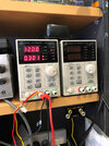
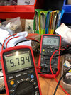
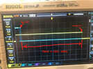
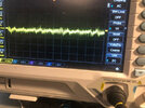
Ok another quick test run, this time got the scope set up better: 12V in (PSU thru isolated 1:1 power transformer), 5.7V out, but this is measured at the HK3 output not at the end of the USB lead....so thats fine allowing for Vdrop thru the cables. I ran again at 578mA drawing ....which is quite a load.

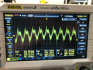
Ripple on the 5V is very low....70mV peak.....110mV PP. Which is more than ok.

My current measurement thru the Ut61E is not the best to use as it has a high Burden voltage (aka it effects the measurement as it too is a load) . I should have used the UT139 it much lower burden.

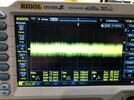
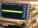
Conclusion....my HK3 is more than suitable for use. The last image just looking at a little induced 60hz hum on the line and switching hash

Oh no matter how much bench space you have....it will be filled with junk....hahaha Sorry I couldn't be bothered doing scope screen grabs it mush easier with a phone camera

IMG_3343small.JPG


IMG_3345small.JPG


IMG_3348 small.JPG


IMG_3349small.JPG
 
Just want to confirm I ran the HK3 voltage cut-off test, set at 12.2V with 12VDC in Idraw at 280mA (resistive load) . Powered up at 12.0V DC, removed the accessory power wire...the HK3 cut the power in around 90's repeated twice...same result.

I didn't test other voltage setting...I can if anyone wants me to but I kinda see little need as ..."it works" within around .1~.2V DC of specified. That's pretty good.

The delay is obviously a hysteresis built in to filter our spurious Vdroop triggering.

So yeah, IMHO its not a bad voltage sense/cutout system.

Brendan

EDIT:
Scope screen Shot Showing Accessories pwr off and time to system cutout.

IMG_3379 SMALL.JPG
 
Last edited:
Long weekend and internet issue did me no good.
Didn't want to keep anyone interested waiting, here are some figures, i might pretty the data up later...

Power in (W)Power out (W)Efficency (%)Ripple (mV pp)Vmin (V)Vmax (V)Notes
HK3 #1 .5A
3.2​
2.61​
81.56​
1580​
4.44​
6.04​
Powers Navman dashcam
HK3 #1 1A
6.9​
5.35​
77.54​
2280​
4.2​
6.52​
Fails to operate Viofo A129 Pro Duo for more than ~ 40 seconds on average.
HK3 #2 .5A
3.2​
2.59​
80.94​
1750​
4.32​
6.04​
Powers Navman dashcam
HK3 #2 1A
7​
5.3​
75.71​
2430​
4.04​
6.49​
Fails to operate Viofo A129 Pro Duo for more than ~ 20 seconds on average.
HK3 #3 .5A rep1
3.17​
2.73​
86.12​
21​
5.44​
5.52​
Vmax too high in my opinion
HK3 #3 1A rep1
6.52​
5.44​
83.44​
19​
5.4​
5.51​
Vmax too high in my opinion
HK3 #4 .5A rep2
3.2​
2.77​
86.56​
21​
5.48​
5.56​
Vmax too high in my opinion
HK3 #4 1A rep2
6.61​
5.53​
83.66​
22​
5.48​
5.56​
Vmax too high in my opinion
HK3 CVDV .5A
3.26​
2.81​
86.20​
22​
5.56​
5.71​
Vmax too high in my opinion
HK3 CVDV .1A
6.7​
5.6​
83.58​
23​
5.56​
5.68​
Vmax too high in my opinion
HK3 Beac .5A
3.15​
2.7​
85.71​
22​
5.36​
5.44​
HK3 Beac 1A
6.48​
5.32​
82.10​
22​
5.28​
5.36​

Each unit tested twice, once at 0.5A and again at 1 amp.
I'm relieved to see the lousy figures aren't the norm.
From where i stood it looked like that could have been the case seeing a unit that does power a camera with lower demands and almost powers the A129.
On replacement #1 and 2, as well as 2 samples sent in the efficiency is around the 85% mark which is reasonable, all units comfortably above 80% .
Vmax is frankly too high on units rep2 and CDDV, but not obscenely so.
Just for something that has a known line length and with a reg that has an output line drop compensation function we really should be able to see 5.00v +/- 5% repeated with ease.
Remember this is the voltage as it arrives at the camera after any losses in the cable, at the output of the reg it will be 100-200mV higher.
Ripple is well under control now which is good to see.
I'd offer to test the stock of the guy that was the original source, but i'm frankly broke $$$, and my back is playing up again, so i might make the offer via dad to the seller to bring them here if he wants.

Need to hurry off.
 
Since the A119 emerged, Viofo cams have been power-hungry if you wanted reliability. But that's becoming more commonplace with multi-channel cams and 2K & 4K cams as I've discovered while trying to re-use existing PS equipment. For years I could just swap cams around but not any more.

Might be nice if there was testing done with all the PS's and HWK's to find max output and best regulation, but that would be lots of work and that's too much to ask of anyone. I wouldn't mind buying something really good just to save me all the wiring work :rolleyes:

Phil
 
Need to hurry off.

Many many thanks you have done an excellent job and ths is good infor not just for end users but for manufacturers. The too need tech feedback from capable techs that highlight issues like this. Once again "salute".

A question.....what is the chipset of the replacement HK3s?'.......the ones that work ok....aka the NDP1335 buck converter units?

Also thanks to who sent you the HK3s to test ...that was Viofo? Thanks to them. I'll post up when I get my electronic load I really cannot help anymore till i do so. But my figures so far are fine.

Cheers, sorry for your spine pain......I'm of course one that can understand this.....

Brendan
 
Last edited:
Since the A119 emerged, Viofo cams have been power-hungry if you wanted reliability. But that's becoming more commonplace with multi-channel cams and 2K & 4K cams as I've discovered while trying to re-use existing PS equipment. For years I could just swap cams around but not any more.

Might be nice if there was testing done with all the PS's and HWK's to find max output and best regulation, but that would be lots of work and that's too much to ask of anyone. I wouldn't mind buying something really good just to save me all the wiring work :rolleyes:

Phil
I'd be happy to test anything sent my way and give my opinion on it, though I'm not formally qualified as an electronics engineer.
I forgot to mention it above but i tested one of the HK3's for max power and it shut it self down at 1.8 amps.
The reg on paper is rated to 3 amps but shuts down at 1.8 when i apply a load.
It may be configured for over current protection at lower than the usual 3Amp point.

Many many thanks
A question.....what is the chipset of the replacement HK3s?'.......the ones that work ok....aka the NDP1335 buck converter units?
Also thanks to who sent you the HK3s to test ...that was Viofo? Thanks to them. I'll post up when I get my electronic load I really cannot help anymore till i do so. But my figures so far are fine.
Cheers, sorry for your spine pain......I'm of course one that can understand this.....

Brendan
Viofo from the forums sent 2 replacements, reminded them i only needed one as we we just unlucky enough to get 2 sequential failures, but i think they actioned it before they got that message.
Still no word or acknowledgement for Viofo Australia, not going to chase it, they might even be aware it's been sorted. Super fast, no stuffing around.

Would have just been nice to know they acknowledge what happened and that they want to help or that they are aware their HQ helped.

Chipset is the NDP1335- interesting to note on the failed units the voltage divider resistors are... strange.
First they don't match the healthy units in value, second they don't even match their face value.
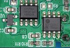
Here is a pic of the failed unit...
HK3PCBs.jpg
R10 and R11 are the divider, and are marked 27D (D for dog i think) and 85D.

Resistor marked 27D measures 186K out of circuit
Resistor marked 85D measures 724K out of circuit

Got somewhere to be so going to have to cut it there.
 
Last edited:
I've read a few thread about the HK3 parking mode issues....I kinda get the feeling that these under performing versions are the root cause. Of course....thats anecdotal...but just get a feeling.....

And what is that part numbering?

Cheers

Thanks V81
 
The reg on paper is rated to 3 amps but shuts down at 1.8 when i apply a load.
It may be configured for over current protection at lower than the usual 3Amp point.
You normally need to add extra cooling to get sustained maximum output from a regulator. Also depends a lot on the input and output voltages, and the amount of voltage drop.
 
With those resistors so far out of spec it's no wonder there's a problem. If @viofo hasn't changed suppliers maybe he should- this at least needs to be investigated.

It could explain a lot of the semi-random issues we've hear about ;)

Phil
 
First they don't match the healthy units in value, second they don't even match their face value.
Here is a pic of the failed unit...
View attachment 56153
R10 and R11 are the divider, and are marked 27D (D for dog i think) and 85D.

Resistor marked 27D measures 186K out of circuit
Resistor marked 85D measures 724K out of circuit

Got somewhere to be so going to have to cut it there.
Haven't checked the "healthy values" yet but 27D means 187kΩ and 85D means 750kΩ. This is an alternative to "normal" marking, I don't see a problem...

EDIT: OK, checked. First of all, now i noticed that the reference circuit in datasheet isn't properly "wired" and some connections look like they are not meant to be connected together and some of them look like they should be connected. (could be the issue as well?) Anyway, although the voltage divider in HK3 uses different values, the division is properly chosen and FB bias is 0.2μA...
 
Last edited:
Seen a lot of SMD marking but never resistors like that...EIA codes.....thanks

v81 indicated that indeed that is what he measured them at. Its just a divider network.

Cheers
 
Must admit, first I've heard of EIA codes.
Seems they might be handy for marking 1% resistors without using 4 characters on the resistor.
That 750K is... just a bit off though, if within spec it should be no less than 742,900.
 
Ok got my DP24 electronic load....jave no idea how to use it....but I suspect if I press enough buttons it'll work.

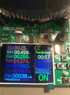
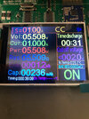
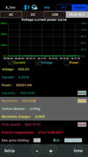
I managed to run at 500mA load and 250mA this is a screen grab of 250mA. Haven't connect CRO to the load to look at the ripple but im sure its ok from last tests....but lets wait and see.

More tomorrow....if I can figure it out! I download the BT interface it appears to work....maybe using that is easier. Fan isn't running...maybe the load is just too small atm. Looking for the manual now....urrrggghh.

Brendan


DLP24 FIRST RUN HK3 .25A SMALL.jpg
 
ok quick update using new active load to get results from my HK3:
CC mode (constant current load)

250mA set,
5.505V out
.251A drawing
1.38W
1.3Wh.

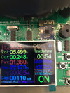
500mA set,
5.499V out
5.00-4.997A drawing
2.73~2.76W
1.2Wh.

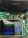
1000mA set,
5.50V out
1.00A drawing
5.506W
1.3Wh.


Ripple was no worse if not better than before but measured at the load not at the HK3 electronics. I tested my Apple power adapter and Laptop power brick.....60 watts....19v.....worked great.

I could also control the load via an iphone App. Worked well but quirky couldn't scale graphs etc. Supposed to be a computer app but...meh couldn't find it...

So in conclusion My HK3 is fine
 

Attachments

  • IMG_3441small.JPG
    IMG_3441small.JPG
    76.3 KB · Views: 10
  • IMG_3442 small.JPG
    IMG_3442 small.JPG
    68 KB · Views: 8
  • IMG_3429 small.JPG
    IMG_3429 small.JPG
    120.2 KB · Views: 9
  • IMG_3426small.JPG
    IMG_3426small.JPG
    130.3 KB · Views: 10
  • IMG_3424 small.JPG
    IMG_3424 small.JPG
    114.2 KB · Views: 11
  • IMG_3436small app.jpg
    IMG_3436small app.jpg
    95.9 KB · Views: 11
Lots of this technical stuff is over my head, but I am doing my best to read over it. Sorry if I sound like a fool, but where is the setting/feature for me to adjust related to the voltage cut-off? I have the Viofo A129 Pro Duo and it is in my race car. one day after using the car I accidentally left the car's main battery on/off switch on, and the camera was running for 4 days just loop recording in 4k front and Full HD rear. It drained my car's battery to about 10.2 volts. I looked through the menus of the viofo camera and can't find anything about power supply cut-off settings. I do have the Hard wire kit, and do not use a usb adapter or anything.

Also, unrelated, but maybe related? The camera keeps intermittently turning on and off the display (and playing that "welcome" chime noise) as I am driving down the road or racing. I have the G-meter turned off, and all my electrical connections are very good. The car is a bit rigid, but I can't see it causing the camera to randomly turn on and off.
 
Back
Top