Hillbilly
Well-Known Member
- Joined
- Feb 14, 2013
- Messages
- 1,755
- Reaction score
- 256
- Location
- Sunshine Coast
- Country
- Australia
- Dash Cam
- DR750s x2 DR450 x2
Ill chime in here as I have done a few of these Firstly as far as I know the CORRECT way to insert an Addafuse is diagram A and only that way.
Why because if the camera trips the fuse the other things originally on that fuse will still work.
If you do it the other way and it has a higher rated fuse the camera could go on fire and burn your car to bits without tripping the high rated fuse.
Remember the fuse is to protect the car against the appliance not the other way around.
Secondly Blackvue cameras already have a fuse in the ciggy plug. Therefore I usually buy one of them and hook it to the wire on the addafuse.Most of the cameras run a 2 amp bullet fuse and stick a 2.5 amp in the top of the addafuse. If they arent available I use a 5 amp.
Havent had any trouble in about 5 different makes with 5 different BV cameras.
In my VW's which are very fussy with circuits i metered out the hot side in spare fuse sockets and worked out which were always on and which were ACC. A bit tricky as some ACC circuits stay live for up to 30 mins. So I stuck the probe in till I found the Live ones with ignition OFF and marked them. Then turned IGN on and found the new ACC on ones and marked them differently. Turned car off and and had a coffee for 45 mins and went back and remetered the ACC ones They were mostly dead and so turned IGN back on and livened them up. So then you use one of the always on and one of the ACC ones that turned off to power your Power magic or whatever.
Crimp or solder all connections and NEVER EVER jam wires down the side of fuse legs.
When I am extending a pair of wires I bare one wire and then leave about 30mm and bare the other one. Solder both and heatshrink them individually.
Sometimes I also put a larger heatshrink over the whole join.
There are apparently some addafuse which are wired differentlyas discussed ??? in this thread
https://dashcamtalk.com/forum/threads/fuse-taps-using-the-hot-side-aka-wrong-side.16700/page-5
However in all of my many years I have yet to come across one.


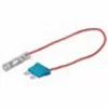
To test one Put a fuse in the top slot and see if there is voltage at the end of the wire If so its in the right way and working properly If no voltage turn it around in the socket and test again as not all cars are wired exactly the same.
EG power from top or left would probably be considered normal
Why because if the camera trips the fuse the other things originally on that fuse will still work.
If you do it the other way and it has a higher rated fuse the camera could go on fire and burn your car to bits without tripping the high rated fuse.
Remember the fuse is to protect the car against the appliance not the other way around.
Secondly Blackvue cameras already have a fuse in the ciggy plug. Therefore I usually buy one of them and hook it to the wire on the addafuse.Most of the cameras run a 2 amp bullet fuse and stick a 2.5 amp in the top of the addafuse. If they arent available I use a 5 amp.
Havent had any trouble in about 5 different makes with 5 different BV cameras.
In my VW's which are very fussy with circuits i metered out the hot side in spare fuse sockets and worked out which were always on and which were ACC. A bit tricky as some ACC circuits stay live for up to 30 mins. So I stuck the probe in till I found the Live ones with ignition OFF and marked them. Then turned IGN on and found the new ACC on ones and marked them differently. Turned car off and and had a coffee for 45 mins and went back and remetered the ACC ones They were mostly dead and so turned IGN back on and livened them up. So then you use one of the always on and one of the ACC ones that turned off to power your Power magic or whatever.
Crimp or solder all connections and NEVER EVER jam wires down the side of fuse legs.
When I am extending a pair of wires I bare one wire and then leave about 30mm and bare the other one. Solder both and heatshrink them individually.
Sometimes I also put a larger heatshrink over the whole join.
There are apparently some addafuse which are wired differentlyas discussed ??? in this thread
https://dashcamtalk.com/forum/threads/fuse-taps-using-the-hot-side-aka-wrong-side.16700/page-5
However in all of my many years I have yet to come across one.
To test one Put a fuse in the top slot and see if there is voltage at the end of the wire If so its in the right way and working properly If no voltage turn it around in the socket and test again as not all cars are wired exactly the same.
EG power from top or left would probably be considered normal