HK3 hard wire kit - terrible voltage regulation

User V81 sent me some HK3's
Glad to see you had a good play with #1

This was the original my parents got with their camera if I recall.

Interesting to hear it actually powered your camera successfully... what is the current draw on your camera, and is it HD / QHD / 4K and dual or single?

A129 Pro Duo is the specific model of Dad's unit, i think that's 1440p front and 1080p rear.

I do find the model numbers pretty annoying as they have in total about 6 different variants of the "129"


On another note, brother has recently installed a Viofo unit, and he quite likes it.
Despite these issues that popped up I'd still probably go with one.

Would love to see 12v direct to camera be done, I suspect then that this would allow Viofo to implement good regulation on board and in the camera rather than dealing with a 3rd party manufactured kit.
Blackview seem to do this already with good success.
 
A129 Pro Duo is the specific model of Dad's unit, i think that's 1440p front and 1080p rear.
It's 4K front.
 
Generally just powered the front A129 using same parameters i get with my A129 front camera powered:
5.V-5,7V DC. 1Amp to generally 700~600mA.....and using resistive load I only had enough resistors for around 9.7Ohms so HK3 out was 5.4V and 570mA. I didn't see much sense in trying to run it at 1.5A as at 1Amp the noise didn't change.

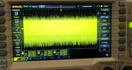
I did set the active load to "Constant Resistive load" 10 ohms. Its results below, 5.47V @ 544mA

So yeah compared to my HK3.....it was a quantum more noise. Now to see if i can attenuate it. I wanted to be sure i wasn't doing anything to "Induce noise" by trying so many different tests! Like a stray light Hum, or transformer hum...its not its the HK3

I'll try one last test at 1.2Amps...just emulate the rear connected but already ran these tests at 1A.


IMG_7508 smal CR load.JPGIMG_7509 CR load noise .JPG
 
Last edited:
Sorry yes 4K front

I did fiddle different parking modes with the USB power device…..not a lot of change in power drawn. Wifi draws an extra 100mA or do.
 
Just a quick update

2 things. Tapping the PSU induced "hell noise and oscillations". I re-soldered (proper lead solder 63/37 and proper rosin flux...yeah old school) all...now good.

I replaced the output capacitor C3 (a solid electro type i think...hell to remove) with std electro's. Most electros i have are usually low ESR (been fixing switchmodes before). Using Resistive load @576mA I draw from HK3, @ 5.6V out (approx on all tests) .

To Cut to the chase removing C3 and putting in a known good 470uf low ESR i achieved .....260mV PP AC couple (a huge drop from above 630mV PP+)

But DC couple test i saw 1V PP! Kinda wondering why (sure i change scales must be allowing better measuring) .
Replacing this with a 330uf cap saw around 221mV PP AC coupling.
Replacing with a 220uF electro, noise now 180mV PP avg and DC coupled noise less than 1 V PP generally 800-900mV. Which is close to my old working HK3

So looks as if i need to tune cct with appropriate electro also look at the ceramic across the output C9...to see if this has effect (it should....ceramics are used to reduce "noise").

Much more to do but looks like soldering and parts issue. I've yet to test the C3 i removed. I now have a reason to use my DE5000 ESR meter! I rarely get a chance....just toss caps and replace on spec. This is an excellent ESR/Inductance and low resistance and resonant Q meter you can get for cheapish price. My first real use of it! Whats the best it takes me an hr to figure out how to use it,.
 
Whats the best it takes me an hr to figure out how to use it,.
And some say he's still figuring it out today!

LOL... G'day mate.
Just had an email re another potentially good HK3 failed in service and came back here to check some history.
Still tempted to build a bulletproof reg from scratch and produce it in small qtys.

I wonder if there would be a market for it.
Seems even the units that work only just barely work, have high voltage and potential to die or kill the attatched camera over time anyway.
The voltages i got, measured at the end of the USB cable were always >5.5v and with 3v3 and 1v8 linear regs in the Viofo cameras this absolutely is equal to an extra watt or 2 of heat, which in a closed non actively cool device like a dashcam... that's a lot.
I'd rather be seeing 5.1 to 5.2 at the input of the camera.
 
Bobcat was making one but stopped. By all indications it was pretty good! If you do consider a parking voltage controller maybe also throw in an input for battery backup (with diode or Fets for steering "stop back feed"). I know.....there is no substitute for std car battery but these days in hybrids this battery capacity is much less than the older 12V std car batteries. I read many Toyota hybrids were killing their 12V battery. This was because the battery used is 1/4 if not less then the STD car batteries. They run everything from the EV (HV) battery so just throw in a small 12V battery for owners and legacy 12V devices. Dash cams are killing these 12V batteries as they have little capacity.

Its quite funny dealers flogging dashcam fitments to new owners not telling them parking mode will drain their battery. Owners getting peeved off as they wanted parking mode!

The Buck voltage regulator NPD1335 has Feedback compensation. Which is just a resistive voltage divider to adjust for long cable run Vdrop. So I guess they measured the resistance of the longest cable and current passed. They appeared to have set a Vdrop (divider is 680k/154K) of around .7mV to .8mV.

I'm guessing the power cable is 20AWG (.5mm^2), max or nominal current is .8A (but i measured this as mostly .5A). If cable is 5mtres then that's 5m to camera and 5m back...the vdrop calculator has it as .3Vdrop

So i probably have cable size wrong. .No idea why they are dying It should be perfectly fine to run or set it to 5.2V out. I wrecked one of my camera USB ports. One 10pin one 5 pin. Luckily I wrecked the 5 pin, so easy enough to fix.

cheers
 
and with 3v3 and 1v8 linear regs in the Viofo cameras this absolutely is equal to an extra watt or 2 of heat,
Do you know that they are using linear regulators, or is that an assumption?
 
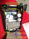
not entirely sure they have a big arse heatsink and under that is another shield.. I didn't lift that shield. The camera is attached by flex etc
 

Attachments

  • IMG_6988 smaller.JPG
    IMG_6988 smaller.JPG
    302.5 KB · Views: 8
Just had an email re another potentially good HK3 failed in service and came back here to check some history.
HK3 was updated and Viofo updated also the HK4 to HK5.

Even before, Viofo hardwire kit was at very good quality. Now, updated is even better even I don't know what exactly they were updating, but I expect at least one diode was attached after I made a suggestion about it. But for more upgrades, I don't know.
 
Do you know that they are using linear regulators, or is that an assumption?
That's an assumption and certainly could be wrong.
That said it's a very resonable assumption and if i had to bet one way or another I'd lean with linear.
Yes, good switch mode regs exist that will do 5v to 3.3v but i don't see it being done in practise.
I'm not going to get in a debate, I've already clearly said it's an assumption and sorry of it comes across as rude but until proven otherwise I'm going to err on my experience and educated guess based on other consumer electronics.
I've already blocked one person for a stupid circular bull**** argument, rather not do it again, and apologies in advance if that was not the direction you were headed in.
It's not an unfair question, really not, I'm just going with my experience.
HK3 was updated and Viofo updated also the HK4 to HK5.

Even before, Viofo hardwire kit was at very good quality. Now, updated is even better even I don't know what exactly they were updating, but I expect at least one diode was attached after I made a suggestion about it. But for more upgrades, I don't know.
Have not seen a HK5 but can confirm the HK4 is the same as the HK3, just dressed differently.
I wouldn't say they were good quality, they might be adequate most of the time, but the PCB is objectively crude and it's not like they are using anything but the cheapest nastiest capacitors they can get.
No Nichicon, Panasonic, etc.. etc.. anywhere to be seen.
The IC is a fairly generic device from a chinese company and if i recall correctly there was no english datasheet.

Each to their own, but for a circuit to be called quality it should have a PCB designed with best practices and with regard to EMI, should use a good quality and well documented IC, say something from the bigger names, in this context I'd probably say MPS, Use good capacitors, and have an output that does not straight up break USB spec when a USB connector is on the end.

This board doesn't meet any of those benchmarks, the HK5 might, have not seen it yet, but if the HK3 and HK4 fall short of the mark then am i unreasonable for assuming the HK5 will fall in the same boat?

With everything, totally happy to be wrong, I'm just applying resonable and logical assumptions based on existing samples and experience with similar electronics built down to a price point rather than up to a standard.
This thread turned into a ****show previously, not going there again.
 
That's an assumption and certainly could be wrong.
That said it's a very resonable assumption and if i had to bet one way or another I'd lean with linear.
Yes, good switch mode regs exist that will do 5v to 3.3v but i don't see it being done in practise.
Considering that the Sony Starvis 2 sensors operate internal logic at 1.1V and Novatek processors use 1.0V, using a linear regulator to convert the ">5.5v" would increase power consumption by around 5x. If we could have parking mode last 5x longer, just by swapping to a switching regulator...

I'm not going to get in a debate, I've already clearly said it's an assumption and sorry of it comes across as rude but until proven otherwise I'm going to err on my experience and educated guess based on other consumer electronics.
The only problem was that you presented your assumption as a fact, making it appear "absolutely" certain that there is some very poor design inside the dashcam. I find it rather unlikely that they are wasting that much power, but I'm not saying that you are wrong, because I don't know. I was just questioning if you knew, or were just assuming.

this absolutely is equal to an extra watt or 2 of heat, which in a closed non actively cool device like a dashcam... that's a lot.
 
  • Like
Reactions: Mtz
Considering that the Sony Starvis 2 sensors operate internal logic at 1.1V and Novatek processors use 1.0V, using a linear regulator to convert the ">5.5v" would increase power consumption by around 5x. If we could have parking mode last 5x longer, just by swapping to a switching regulator...
Last few various cameras i pulled apart had a 3v3 and 1v8 linear regs for various sub systems, dont recall exact models nor sensors.
Quite fair the Starvis uses 1v1 and the cpu otherwise, but a few of the internals will also be using the full 5v or possibly 3v3, the 129 pro duo seems to use input voltage this for it's display backlight based on reaction to changing input voltage.
I don't know what current the sensor or SoC use specifically, but sure would be much more efficent and very good practice to use efficent and good quality switching regs for these subsystems.

The problem i have is that even when it would be obvious to do so i rarely see best practice out in the wild of cheap consumer electronics.

In an ideal world i would 100% love to assume that ever product, big or small is crafted to the highest standard with the best practices available.

Here on earth for all practical discussion I'll fall back to my practical experience.

And this isn't a knock to Viofo. Just about every company that brings electronics to market are guilty of Muntzing their products to varying degrees to simplify and/or reduce cost.
I do it to a limited degree myself to simply designs, usually just backing off on having excess bypass capacitors is only about as far as i go.

Let's be clear, I *WANT* to assume that Viofo use switching regs.
But again as i say I'm just operating with the practical experience i have, in a vacuum without an answer.
I don't own a single Viofo product, never have... I just ended up here as a result of having 2 back to back wildly and verifiably faulty HK3's as part of a chain of issues with my fathers cam install.
And going back to see myself being attacked for showing these failures and finding more in the wild pisses me off when all i did is document what i found, the good and the bad.
So pardon me if i've coming across a bit sour.

As for the assumptions, many things are assumed in day to day life, the sun will some up tomorrow etc... they are ultimately inconsequential however to the issue at hand.
If you have anything to add aside from attacking these assumptions, be my guest.
If you have a unit you can pull apart then go for it, i'm always open to new information and can certainly change my views.

The real issue is that many more of these HK3's are out in the wild possibly on the verge of vailure, and it's possible i might have found another.
So for now lets drop the cam issue, this thread isn't even about that... every viofo cam i've run from a good clean 5v source has functioned perfectly.
I only concern myself with the power architecture inside a little as the power they draw is pushing the limits of the HK3/HK4.
As i've said i've not seen a HK5.
 
Have not seen a HK5 but can confirm the HK4 is the same as the HK3, just dressed differently.
I wouldn't say they were good quality, they might be adequate most of the time, but the PCB is objectively crude and it's not like they are using anything but the cheapest nastiest capacitors they can get.
No Nichicon, Panasonic, etc.. etc.. anywhere to be seen.
When I say quality for me means that the hardware kit is not failing. I heard very very rare about a failed hardwire kit from Viofo. And when it failed was because it was covered with car carped insulation and it became too hot because of no cooling and also were problems when contacts were lose at the fuse tap connection. Other cases I don't know.
If the product is working as expected and not failing at least in the 2 years EU warranty this means the product is OK. But the Viofo hardwire kits are not failing soon after 2 years, I have two installed in my car for more than 5 years: one HK3 and one HK4. I will replace them with the new versions from this photo:

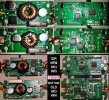
Viofo hardwire kit - upgrade.jpg

The comparison picture was made from a factory sample of the new versions of hardwire kits. I am not a specialist in photography or electronics but when looking at the whole product just think that the factory price I expect to be under $5. At this price is not possible to put Nichicon, Panasonic or other brands if the product is working as expected.

You can zoom in the picture for more details and it is uploaded also here.

I think the main goal for the upgrade was less power consumption in standby mode and the added diode to not return voltage on ACC.
 
When I say quality for me means that the hardware kit is not failing. I heard very very rare about a failed hardwire kit from Viofo. And when it failed was because it was covered with car carped insulation and it became too hot because of no cooling and also were problems when contacts were lose at the fuse tap connection. Other cases I don't know.
Well you know of 3 other cases from this thread alone that you have neglected to mention, and 2 of these were for units never installed, dead out of the box.
The number of people that want to ignore the evidence of the failed units i have is concerning.
The scope traces don't lie.
I'm happy to attribute these units to bad luck, also happy to assume this is not common, but still there were at one point 3 of 5 units on my bench that were dead. Common or not that's a pretty big deal at least locally.
..I am not a specialist in photography or electronics but when looking at the whole product just think that the factory price I expect to be under $5. At this price is not possible to put Nichicon, Panasonic or other brands if the product is working as expected.
As for capacitors.. crappy ones cost 10 cents.. good ones cost 40, and thats at terrible low volume pricing that i get.
And for the type of component that has electrolyte that can dry out and age poorly if corners are cut they are not worth cutting costs on.
When bought in reels of 5000 units, still from my overpriced local supplier we're talking AUD $ 0.12 per unit.
So if their BOM went up 20 cents to improve the 2 components on the board most likely to cause issues over time who cares?
We're talking an increase in production cost of 20 damn cents. Not a dollar or 2.
For something sold here locally for AUD$35 last i checked cutting 20 cents off the BOM is penny pinching.
Switching the IC for something more reliable would make a larger impact to the cost, but still not unreasonably so.
 
Last edited:
Bobcat was making one but stopped. By all indications it was pretty good! If you do consider a parking voltage controller maybe also throw in an input for battery backup (with diode or Fets for steering "stop back feed"). I know.....there is no substitute for std car battery but these days in hybrids this battery capacity is much less than the older 12V std car batteries. I read many Toyota hybrids were killing their 12V battery. This was because the battery used is 1/4 if not less then the STD car batteries. They run everything from the EV (HV) battery so just throw in a small 12V battery for owners and legacy 12V devices. Dash cams are killing these 12V batteries as they have little capacity.

Its quite funny dealers flogging dashcam fitments to new owners not telling them parking mode will drain their battery. Owners getting peeved off as they wanted parking mode!

The Buck voltage regulator NPD1335 has Feedback compensation. Which is just a resistive voltage divider to adjust for long cable run Vdrop. So I guess they measured the resistance of the longest cable and current passed. They appeared to have set a Vdrop (divider is 680k/154K) of around .7mV to .8mV.

I'm guessing the power cable is 20AWG (.5mm^2), max or nominal current is .8A (but i measured this as mostly .5A). If cable is 5mtres then that's 5m to camera and 5m back...the vdrop calculator has it as .3Vdrop

So i probably have cable size wrong. .No idea why they are dying It should be perfectly fine to run or set it to 5.2V out. I wrecked one of my camera USB ports. One 10pin one 5 pin. Luckily I wrecked the 5 pin, so easy enough to fix.

cheers
Hey, thanks for acknowledging my efforts on this! I see there is still a lot of interest around a good hardwiring kit and that's encouraging!
I am happy to share my view on the topic, and why I sort of dropped out from further development (although I have some new ideas for a board that can "do it all").

The main reasons why I've halted the development of my project:
1. Such a board, if using high quality components, let's say from TI for power handling, makes it much more expensive to produce in low numbers.
2. Chinese manufacturers/ assembly shops often don't have access to these components, so some parts would have to be added manually after the main assembly.
3. Adding more features and different parts from the original hk3/4 would require custom enclosure (3d printed in low volumes in my vision). Although doable, but very time consuming.
4. While I can offer to the market a custom regulator board, the peripherals, such as wiring from the car to pcb and from pcb to the camera would have to be arranged by potential customers (which means soldering by the customer). Offering a "plug and pay" solution is impossible in lower volumes. And low volumes would mean hundreds of these boards.
5. Each board would have to be programmed and QCd manually.

I do know there are a lot of enthusiasts on this forum, but even if every single one of you bought such a board from me, I'd probably just break even, after spending hundreds of hours of developing and assembling it. Lower volumes would mean I'd do all that at my own loss (mainly time). Now that being said, I'm exploring a new idea I have in mind, mainly for enthusiasts and without commercial aim and if I manage to find the parts needed to make it happen, I'll be making a new update on this project soon.
 
Seems that the horrible title of a good product was used for promoting a personal product which finally failed as a project.
Again: good means that is not creating problems to the dashcams or to the cars and RMA, DOA, returns are minimal.
If my HK3 hardwire kit from Viofo is working as expected, not creating problems even it is used for more than 5 years I don't see a reason to buy another product more expensive from an unknow seller. But maybe other people could buy your hardwire kit just because you will present it as made with quality components. Some people can be happy to know that they have the best from the market even the result is the same.

Good luck with your new idea but I hope to present it as an idea and not to blame a good product just to promote your idea.

For now I will replace the old HK3 even it is working like in the first day with the new version of HK3 which was showed in my previous post. I hope the new version to be durable as the first version and last it for another 5 years. If not, I will mount the old HK3 again. I will keep it as backup because never failed on me. I am sure the new HK3 version and the HK5 are better than previous versions, the PCB is looking better.
 
For now I will replace the old HK3 even it is working like in the first day with the new version of HK3 which was showed in my previous post.
I'm trying to understand the rationale for replacing a working unit?
What's going on here?
What do you hope to gain by switching one HK3 with another?
 
To test it, to see if the new version is better than the old version. I am testing things for more than 10 years on this forum. As I said, I will keep the old HK3.
At this moment I have 4 hardwire kits installed on my car, one HK3 and three HK4 which will be replaced with HK5. On 3 hardwire kits (2 HK4 and one HK3) I am using switches to avoid battery drain by 4 hardwire kits connected to my permanent fuses. I expect the new hardwire kits to drain less power in stand by, when camera is not recording in Parking Mode.
 
Back
Top